Abb.
schéma 1
für
Schrauben
Ø
In Holz und Kunststoff
ohne Metalleinlage
Bohrer Ø
In Alu und Kunststoff
mit Metalleinlage
Bohrer Ø
4,0 mm
3,0 mm
4,5 mm
3,0 mm
5,5 mm
4,2 mm
D Montage- und Bedienungsanleitung für ABUS Fenster-Universalschloss FTS
G ABUS Installation and operation instructions for ABUS universal window lock FTS
F Instructions de montage pour serrure de fenêtre universelle ABUS FTS
1 x
1
IV Montagewerkzeug
• Kreuzschlitzschraubendreher
• Schlitzschraubendreher
• Bohrmaschine
• Feile, Säge zum Kürzen der Schrauben, ggf. Schraubstock
• Inbusschlüssel SW
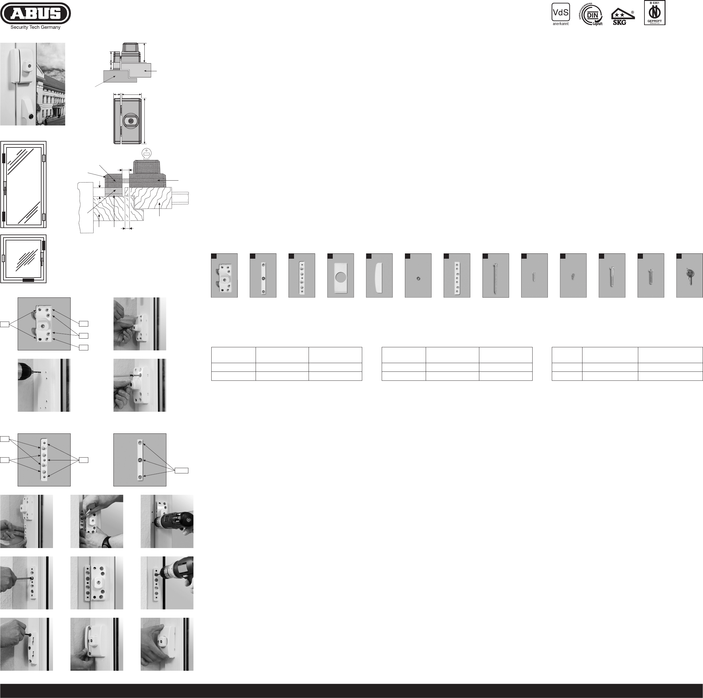
Bohrtabelle
V Montage
Wichtige Hinweise:
1. V
Stellen Sie sicher
lässt.
2. Messen Sie auch nach, ob die in Abb.
Ihrer Fenstertür vorhanden sind.
3. Die Bohrlochtiefen bzw
abgestimmt werden.
4. Austreten des Bohrers bzw
Ggf. mit Bohranschlag arbeiten oder die vorhandenen Schrauben kürzen.
Beim Bohren keine beweglichen T
Montage des Schlosskastens:
Abdeckhaube (4) vom Schlosskasten (1) durch Druck auf Rastpunkte auf der Rückseite
entfernen. Riegel ausschließen.
Schlosskasten (1) in gewünschter Position auf Fensterflügel bzw
Abstand zur Flügelkante 2 mm (s. Abb. 3).
Bohrposition E und F (nur bei Kunststofffenstern und -türen zusätzlich G ) anzeichnen und
vorbohren lt. Bohrtabelle (s. Abb. 4 + 5).
Schlosskasten (1) anschrauben. Bohrungen E (je nach Falzhöhe) Schrauben 4,2 x
oder 4,2 x 9,5 mm (Schraubendreher mit Magnetspitze verwenden). Für Bohrungen F ( G)
Schrauben 5,5 x 60 mm (s. Abb. 4 + 7).
Montage des Schließkastens:
Schlosskasten (1) und Schließkasten (2) müssen auf gleicher Ebene liegen (s. Abb. 3).
Zum Ausgleich der unterschiedlichen Falzhöhen wird der Schließkasten (2) unterlegt.
Hierzu dienen die Anschraubleiste (3) und
Falzhöhe: ab [mit Anschraubleiste (3) und ggf. Unterlagen (7)].
Anschraubleiste (3) (1
von 3 mm zum Schlosskasten (1) anhalten (s. Abb. 3). Auf richtige Lage der Anschraub-
leiste (3) achten (s.
t Abb. 3).
Bohrpositionen A anzeichnen und vorbohren (s. Abb. 8,11, 1 und Bohrtabelle).
Anschraubleiste (3) bei Bedarf (Falzhöhe größer 1
Mit Schrauben 5,5 x 60 mm festschrauben (s. Abb.
Durch die schrägen Schraubenlöcher C im gleichen W
bohren (s. Bohrtabelle). W
werden. Dann in Bohrungen C die beiden keilförmigen Unterlegscheiben (6) einlegen
(s. Abb. +
In Bohrungen C weitere Schrauben 5,5 x 60 mm einschrauben.
Abdeckhaube (5) vom Schließkasten (2) durch Druck auf Rastpunkte auf der Rückseite
entfernen.
Schließkasten (2) mit 3 Schrauben (1
Löcher B schrauben (s. Abb.
Falzhöhe: 0 bis(ggf. mit Unterlagen).
Abdeckhaube (5) vom Schließkasten (2) durch Druck auf Rastpunkte auf der Rückseite
entfernen.
Schließkasten (2) mittig auf gleicher Höhe und im parallelen Abstand von 3 mm vom
Schlosskasten (1) anhalten (s. Abb. 3).
Bohrposition D1 bis D3anzeichnen (s. Abb. 9) und vorbohren (s. Bohrtabelle).
Schließkasten (2) bei Bedarf mit Unterlagen (7) unterfüttern und mit 3 Schrauben (8)
5,5 x 60 mm festschrauben.
Funktion prüfen: Riegel müssen beim Einschließen in den Schließkasten (2) frei laufen.
Bei Montage von FTS 96: beide Abdeckhauben (4 + 5) aufdrücken.
Bei Montage von FTS 96 E: siehe Rückseite
VI. Bedienung
FTS 96 lässt sich ohne Schlüssel durch Drehen des Knopfes verschließen.
Zum Öffnen wird mit Schlüssel entriegelt und der Drehknopf zurückgedreht.
390296 1/09
ABUS - Das gute Gefühl der Sicherheit
www
D T
G Subject to technical alterations. No liability for mistakes and printing errors. ABUS © 2009
F Nous nous réservons le droit de toutes modifications techniques. Nous n’assumons aucune responsabilité pour des erreurs ou défauts d’impression éventuels. ABUS © 2009
G These instructions are organised in the following sections:
I. General instructions IV T
II. Possible uses V Installation instructions
III. Pack contents VI. Operation
I. General instructions
The universal window lock FTS 96 is recognised as complying with the strict test require-
ments of DIN 1
RET
in your rooms. DIN 1
fitted on the left and right for every meter in height (per window).
The police and insurance companies also give the same recommendation.
Optimum protection can be achieved by proceeding according to these installation and
operation instructions. T
screwed in using a suitable tool and tightened by hand. Only use ABUS fastening material.
The manufacturer does not assume any liability for possible injuries or damages caused
during installation and/or by incorrect handling!
II. Application
FTS 96 is mounted on the handle side of the window or French door and is suitable for all
common windows/French doors openingto the inside with turn or turn-and-tilt hard-
ware (fig.
can open to the right or left.
FTS 96 is always fitted on the inside, with the lock case on the casement and the striking
plate on the frame.
In poor fixture conditions (soft or hollow or foam base and PVC windows with and without
metal inlay and wooden windows) and/or good possibilities for intrusion from the outside,
more security devices and additional fastenings should be used (composite mortar or
fixing bolts). If the frame itself is too weak for sensible retrofitting, it may be necessary for
example to reinforce the frame.
TABUS fixing bolt BA or alternatively for PVC frames, the ABUS
fastening set IMFor IM
Hilti or similar
composite mortar
The ABUS products (FAS) shown in fig. 2 are also available from retail stores.
III. Pack contents
1. 1 lock case 08. 8 each 5.5 x 60 mm
2. 1 striking plate 09. 2 each 4.2 x 16 mm
3. 1 screw-on strip 1 2 each 4.2 x 9,5 mm
4. 1 cover cap for lock case 1 1 each M6 x 35 mm
5. 1 cover cap for locking case 1 3 each M6 x 25 mm
6. 2 wedge-shaped washers 1 2 keys
7. 1 set of spacers for the frame strip
F Ce manuel comporte les chapitres suivants:
I. Conseils d’ordre général IV Outillage
II. Application V Instructions de montage
III. Liste de colisage VI. Utilisation
I. Conseils d’ordre général
La serrure de fenêtre universelle FTS 96 satisfait aux exigences de contrôle sévères des
normes DIN
qualification «
par effraction dans votre logement. Selon la norme DIN 1
monter une sécurité complémentaire par mètre de hauteur de fenêtre, à gauche comme à
droite (par fenêtre). La police et les compagnies d’assurance le recommandent également.
Pour un effet de protection optimal, suivez les instructions de ce manuel d’installation et
d’utilisation. Afin d’éviter un serrage abusif, vissez et serrez les vis de fixation à la main
et avec un outillage adéquat. Utilisez exclusivement des accessoires ABUS.
Le fabricant n’assume aucune responsabilité pour d’éventuels blessures ou dégâts causés
pendant l’installation et/ou par suite de manipulations inappropriées!
L
II. Application
FTS 96 est monté du côté de la poignée de la fenêtre ou de la porte-fenêtre et convient pour
toutes les fenêtres/portes-fenêtres courantes, ouvrant vers l’intérieur et pourvues de
quincaillerie battante ou oscillo-battante (schéma
des châssis en bois, en PVC ou en aluminium. Les fenêtres/portes-fenêtres peuvent s’ouvrir
à gauche ou à droite.
FTS 96 est monté en principe du côté intérieur
mant. En cas de possibilités de fixation défavorables (fenêtres en bois ou en PVC), plusieurs
sécurités et des fixations supplémentaires (plots d’ancrage ou mortier) doivent être prévues.
Pour cela, utilisez l’ancre de fixation ABUS BA (pour fenêtres en PVC, en bois tendre ou en
aluminium) ou l’ensemble de fixation ABUS IM
un mortier approprié est requis, par exemple de la marque Fischer
similaire. ABUS BA et ABUS IM
le commerce.
Les produits ABUS complémentaires illustrés en schéma 2 (FAS) sont également disponibles
dans le commerce.
III. Liste de colisage
1. 1 boîtier 08. 8 pièces 5,5 x 60 mm
2. 1 gâche 09. 2 pièces 4,2 x 16 mm
3. 1 platine de fixation 1 2 pièces 4,2 x 9,5 mm
4. 1 cache pour boîtier 1 1 pièces M6 x 35 mm
5. 1 cache pour gâche 1 3 pièces M6 x 25 mm
6. 2 entretoises coniques 1 2 clés
7. 1 ensemble d’entretoises pour dormant chacun 1
1 x
2
1 x
3
1 x
4
1 x
5
1 x
6
1 x
7
Abb. 11
Montage des Schlosskastens / Fitting the lock case / Montage du boîtier
Abb.6
Schlosskasten
Lock case
Boîtier
A
B
C
Anschraubleiste
Screw-on strip
Platine de fixation
D 1-3
Schließkasten
Striking plate
Gâche
Abb. 12
Abb. 17
for
screws
Ø
in wood and PVC
without metal inlay
drill bit Ø
in aluminium and PVC
with metal inlay
drill bit Ø
4.0 mm
3.0 mm
4.5 mm
3.0 mm
5.5 mm
4.2 mm
IV Installation tools
• Phillips screwdriver
• Slotted recess screwdriver
• Drill
• Saw
• 1 hex key
Drilling table
V Installation instructions
Installation:
1. Before installation, please check the setting of the window or French door
readjust the fittings so that the window (French door) opens and closes perfectly
2. Also check whether your window/French door complies with the minimum dimensions
shown in fig.
3. The depths of the drilled holes and screw lengths must be adjusted to the local
conditions.
4. Avoid the drill or screws from coming out at the back!
Possibly work with drill stopper or shorten the existing screws.
When drilling, do not damage any moving parts, seals or glass panes.
Fitting the lock case:
Remove the cover cap (4) from the lock case (1) from below by pressing on the catch
points (see fig. 5). Undo the locking bolt.
Hold the lock case (1) in the required position against the window casement or door
at a distance of 2 mm to the edge (see fig. 3).
Mark and pre-drill hole position E and F (for PVC windows and doors also G)
(see fig.
Screw on lock case (1). For holes E (depending on rebate height), use screws 4.2 x
or 4.2 x 9.5 mm (screwdriver with magnetic tip). Holes F ( G ) screws 5.5 x 60 mm
(see fig. 4 + 7).
Fitting the striking plate:
The lock case (1) and striking plate (2) must be on the same level (see fig. 3).
T
screw-on strip (3) and
Rebate height: from [with screw-on strip (3) and possibly shims (7)].
Hold the screw-on strip (3) (1
of 3 mm to the lock case (1) (see fig.
position (see
t fig.
Mark and pre-drill bore holes A (see fig. 8,11, 1 and drilling table).
Line screw-on strip (3) with spacers (7) if necessary (rebate height larger than 1
Screw tight with screws 5.5 x 60 mm (see fig.
Drill in the middle through the slanting screw holes C at the same angle to the wall
(see drilling table). If this is not possible, drill vertically
washers (6) in holes C (see fig. +
Screw 2 more screws 5.5 x 60 mm into holes C.
Remove the cover cap (5) from the striking plate (2) from below by pressing on the catch
points.
Screw striking plate (2) to screw-on strip with 3 screws M6 x 25 mm (see fig.
Rebate height: 0 to(possibly with shims).
Remove the cover cap (5) from the striking plate (2) from below by pressing on the catch
points.
Hold striking plate (2) centrally on the same level and at a parallel distance of 3 mm
to the lock case (1) (see fig. 3).
Mark and pre-drill holes position D1 to D3 (see fig. 9) (see drilling table).
Line striking plate (2) with spacers (7) if necessary and screw tight with 3 screws (8)
5.5 x 60 mm.
Check function: Locking bolt must run freely into the striking plate (2) when closing.
When installing the FTS 96: Press on both covers (4 + 5).
When installing the FTS 96 E: See reverse side
VI. Operation
FTS 96 can be locked without a key by turning the knob.
Open with the key
pour
vis
de Ø
dans châssis bois et PVC
sans armature métallique
foret Ø
dans châssis aluminium et PVC
avec armature métallique
foret Ø
4,0 mm
3,0 mm
4,5 mm
3,0 mm
5,5 mm
4,2 mm
IV Outillage de montage
• T
• T
• Perceuse
• Lime, scie pour raccourcir les vis, tournevis
• 1 clé à six-pans SW 4
T
V Instructions de montage
Indications importantes:
1. Avant l’installation, contrôlez le réglage de la fenêtre ou de la porte-fenêtre.
Assurez-vous que la fenêtre/porte-fenêtre ouvre et ferme parfaitement.
2. Vérifiez si votre fenêtre/porte-fenêtre comporte les dimensions minimales indiquées
en schéma
3. Les profondeurs de perçage ou les longueurs de vis doivent être adaptées aux
conditions locales.
4. Evitez le dépassement de perçage ou de vis sur la face arrière!
Utilisez le cas échéant une butée de perçage ou raccourcissez les vis de fixation.
Lors du perçage, évitez d’endommager les éléments mobiles, les joints ou les vitres.
Montage du boîtier:
Déposez le cache du boîtier (1) par le bas en appuyant sur des points d’appui
(voir schéma 5). Déverrouillez les pênes.
Maintenez le boîtier (1) dans la position désirée sur le vantail ou sur l’encadrement
la fenêtre. Distance du bord 2 mm (voir schéma 3).
TE et F (et G , uniquement sur des fenêtres
et portes-fenêtres en PVC) (voir schéma 7
Fixez le boîtier (1). Fixations de vis E : (en fonction de la hauteur de rainure)
vis de 4,2 x
Fixations de vis F ( G ): vis de 5,5 x 60 mm (voir schéma 4 + 7).
Montage de la gâche:
Le boîtier (1) et la gâche (2) doivent se trouver à la même hauteur (voir schéma 3).
Pour égaliser les différentes hauteurs du recouvrement la gâche (2) doit être rehaussé.
C’est à cela que servent la platine de fixation (3) et/ou les entretoises (7).
Recouvrement: supérieure à
des entretoises (7)].
Maintenez la platine de fixation (3) (d’une hauteur de
hauteur et à une même distance de 3 mm en parallèle au boîtier (1) (voir schéma 3).
Assurez-vous de la bonne position de la platine de fixation (3) (voir
t schéma 3).
TA (voir schéma 8,11, 1 tableau de perçage).
Rehaussez selon les besoins (profondeur de rainure supérieure à
de fixation (3) au moyen des entretoises (7). Fixez-la avec des vis de 5,5 x 60 mm
(voir schéma
Préforez de biais dans le même angle et au travers des fixations de vis C dans la paroi
(voir tableau de perçage). Si cela s’avère impossible, forez dans le sens perpendiculaire.
Dans ce cas, posez les entretoises coniques (6) dans les trous de fixation C
(voir schéma 1 +
Installez d’autres vis de 5,5 x 60 mm dans les fixations C.
Déposez le cache (5) de la gâche (2) par le bas en appuyant sur les points d’appui.
Fixez la gâche (2) sur la platine de fixation (3) avec 3 vis M6 x 25 mm (voir schéma
Recouvrement: 0 –(éventuellement avec entretoises)
Déposez le cache (5) de la gâche (2) par le bas en appuyant sur des points d’appui.
Maintenez la platine de fixation (2) centrée, à la même hauteur et à une même distance
de 3 mm en parallèle au boîtier (1) (voir schéma 3).
TD1 à D3 (voir schéma 9) et préforez (voir tableau de perçage).
Ajustez la hauteur de la gâche (2) selon les besoins avec des entretoises (7) et fixez-le avec
3 vis (8) de 5,5 x 60 mm.
Contrôlez le bon fonctionnement: Lors de la fermeture, les pênes doivent coulisser
librement dans la gâche (2).
Montage sur la FTS 96: presser sur les deux couverles (4 + 5).
Montage sur la FTS 96 E: voir au verso
VI. Utilisation
La fermeture de FTS 96 s’effectue sans clé, en tournant le bouton.
Pour l’ouverture, la clé est requise.
8 x
8
2 x
9
2 x
10
1 x
11
3 x
12
2 x
13
FAS
FAS
FTS
FTS
FAS
FTS
FTS
F
G
E
G
Abb.5
Montage des Schließkastens / Fitting the striking plate / Montage de la gâche
Abb. 10
Abb. 18
Abb.2
Q = Schlosskasten / Lock case / Boîtier
W = Schließkasten / Locking case / Gâche
E = Anschraubleiste / Screw-on strip / Platine de fixation
U = Unterlagen für Höhenausgleich / Spacers / Entretoises
w = Falzhöhe / Rebate height / Recouvrement 0 29 mm
e = Rahmen / Frame / Cadre
r = Tür bzw
t = Die Schräge an der Anschraubleiste
The slant at the screw-on strip
La partie biseautée doit faire face au mur et non au verrou
Abb. 4
Abb. 7
Abb. 15
Abb. 16
Abb. 13 Abb. 14
3 mm
2 mm
w
E
t
e
r
Q
Abb. 3
U
W
Abb. 9
Abb. 8
Fensterflügel
Window
Battant de fenêtre
Fenster-
rahmen
Frame
Cadre
51
28
max. 29
12
51 3
D Diese Anleitung ist wie folgt untergliedert:
I. Allgemeine Hinweise IV Montagewerkzeug
II. Einsatzmöglichkeit V Montage
III. Packungsinhalt VI. Bedienung
I. Allgemeine Hinweise
Das Fenster-Universalschloss FTS 96 ist nach den strengen Prüfanforderungen der
DIN 1
„EINBRUCHHEMMEND DIN-geprüft“
tigtes Eindringen in ihre Räume. Gemäß DIN 1
Fensterhöhe rechts und links jeweils eine Zusatzsicherung montiert wird (pro Fenster).
Polizei und V
Die optimale Schutzwirkung erreichen Sie, wenn Sie entsprechend dieser Montage- und
Bedienungsanleitung vorgehen. Die Befestigungsschrauben sollten zur V
Überdrehung mit einem geeigneten W
werden. Ausschließlich ABUS-Befestigungsmaterial einsetzen.
Für eventuell auftretende V
durch unsachgemäße Handhabung entstehen, übernimmt der Hersteller keine Haftung!
Ein Zugang des gesamten Objektes muss von außen mittels Schlüssel zu öffnen sein.
II. Einsatzmöglichkeit
FTS 96 wird auf der Griffseite des Fensters oder der Fenstertür montiert und eignet sich
für alle gängigen nach innen öffnende Fenster/Fenstertüren mit Dreh- oder Dr
Beschlägen (Abb.
erfolgen. Die Fenster/Fenstertüren können nach rechts oder links öffnen.
FTS 96 wird grundsätzlich auf der Innenseite montiert, der Schlosskasten auf dem Fenster-
flügel und der Schließkasten auf dem Rahmen.
Bei schlechten Befestigungsmöglichkeiten (W
mehrere Sicherungen und zusätzlich Befestigungsmittel (Befestigungsanker oder
Veingesetzt werden. Hierzu verwenden Sie bitte den ABUS-Befestigungs-
anker BA (Kunststoff-, WABUS-Befestigungsset
IM(Kunststofffenster). Zu IMbenötigen Sie einen geeigneten Verbundmörtel,
z.
V
Die in Abb.
III. Packungsinhalt
01. 1 Schlosskasten 08. 8 Stück 5,5 x 60 mm
02. 1 Schließkasten 09. 2 Stück 4,2 x 16 mm
03. 1 Anschraubleiste 1 2 Stück 4,2 x 9,5 mm
04. 1 Abdeckhaube Schlosskasten 1 1 Stück M6 x 35 mm
05. 1 Abdeckhaube Schließkasten 1 3 Stück M6 x 25 mm
06. 2 Unterlegscheiben keilförmig 1 2 Stück Schlüssel
07. 1 Satz Unterlagen für Rahmenleiste je 1