- ENGLISH -
TRD02B0000SE 026889 180516
Configuration end is indicated with the wording 'End '. Press
'
to normal operation.
At few
configuration menu is quit without saving an
When ' ',
the display shows the current value for that par
Use keys ' ' o ' ' to m the se parameter's
configuration; is quickly decreased
holding the keys' ' or ' ' pressed.
The ' TES ' procedure i autom acti after
configuration
communicates i on the output configuration to the
receiver, which the latter saves in a versatile manner and is
used to adjust the temperature in the wanted m
It i important, therefore, to run self on the receiver
before modifying
receiver ' TEST ' controls
configuration.
Reset installer configuration
To
to values, the configuration when
the Con ', ' or ' for
few seconds until the screen goes back to normal mode.
Description of configuration parameters
The i co parameters a shown in ta
and explained below.
Some parameters not b
current co required parameters are proposed
(the
more subsequent parameters).
P01: all using the thermostat (tr or r (r
heating/cooling mode.
This param modified to ' rEC ' (receiver)
when wanting to use the thermostat in association with a
programmable
external he selection input or economy input of
the New Wave relay modules.
P02: allows to customise the regulation modes that can be
selected '. available
are Comfort,
or disabled by changing P02 .
Economy P01 is
'rEC'.
The P03
is configured with an antifrost t
P03: be
this will be maintained when the ther
The antifrost temperature c
disabled by setting the parameter until the v
By default this parameter is factor
P04: room temperature offset.
The detected r temperature can be correct by ±10.0 °C
with the offset, in order to correct any systematic rea
errors due to therm in uns areas for
detecting the room temperature.
By default the device is set with 0.0 °C offset.
P05: sampling time.
To a long of the batteries, the thermostat waits a
period
as 3 or 10 minutes.
It is therefore normal that the temperature di is not
immediately moreover reason it
necessary t
off.
The 3 minutes op the heating/
cooling system is fast, meanwhile with the common ‘slower’
heating on or even
10 minutes option gives perfect acc
In any c at any time, pressing the ' ' key f an
update of the system.
Choosing the longest interval delivers
P06 and P07: these two parameters confi
range
the P06 is
can P07
higher that can
limit, chosen in P06 , up to 35.0°C.
Therefore,
reduced based on installation requirements.
P08 and P09: these two parameters confi
range
the thermostat is i
previous two points.
The
of
selection P01=rEC ),
will P06 and P07
are always used.
P10: NTC sensor configurat
The
NTC (P10= Int ).
Alternatively to the in
wired B
Fig. and parameter 'Ext': in way
sensor
the proper type for remote sensor, and respect the maximum
wire length allowed.
P11: output PWM adj allows choosi
receiver output must be dr in ON/OFF
COMPATIBILITY WITH NEW WAVE R
The
the following limits on the firmware versions (FW):
DAPF84 (active antenna): all
DAPF84 (repeater): fr FW. 02 and
su
DLP841M (8 channel module) fr FW. 02 and
su
DLP841M001 (8 channel module): all
DLP8412 (8 channel module): all
DLP241M (2 channel module): fr FW. 02 and
su
DLP241M001 (2 channel module): all
D fro
su
D
Subsequent firmware versions are i with a higher
number (excluding final A1).
TECHNICAL FEATURES
Power supply: 2 x 1.5V= alkaline AA type
batteries
Duration of the batteries: 5 y
3
Frequency: 868.150 MHz
Modulation: GFSK
Output power (ERP): < 1 mW
Type of antenna: Internal
Max. d
>50
the building and environment)
Temperature sensor (internal sensor or re
Regulation range: 5.0 .. 35.0°C
Hysteresis: 0.2°C configurable 0.1 .. 5.0 °C
Type of sensor: NTC 4K7 Ohm ±1% @ 25°C
Resolution: 0.1°C
Range: -9.9°C .. +50.0°C
Precision: ±1.0°C
Maximum length of the wires
to the remote sensor: 15 m
Antifrost: 6.0|0.
Offset: ± 10.0°C. (Default 0.0°C)
Backlighting switch-off: 20 seconds from last pressing
Protection rating: IP 30
Insulation class: III
Number of manual cycles: 100,000
Number of automatic cycles:
Software class: A
EMC test voltage: 3V
EMC test current: 35mA
Ball pressure test temp.: 75° C
Operating temperature: 0°C .. +40°C
Storage temperature: -10 ℃ .. +50°C
Humidity limits: 20% .. 80% RH (non-condensing)
Enclosure: Material: ABS+PC V0 self-extinguishing
Colour: Signal
Weight: ~ 115 gr
CLASSIFICATION UNDER REG. 2013.811.EC
Class: IV
Contribution to energy efficiency: 2%
NORMATIVE REFERENCES
The product is conform w(EMC
2014/30/UE e LVD 2014/35/UE):
EN-60730-1 (2011)
EN-60730-2-9 (2010)
ETSI EN 301 489-3 v1.4.1 (2002)
ETSI EN 300 220-2 v2.1.1 (2006)
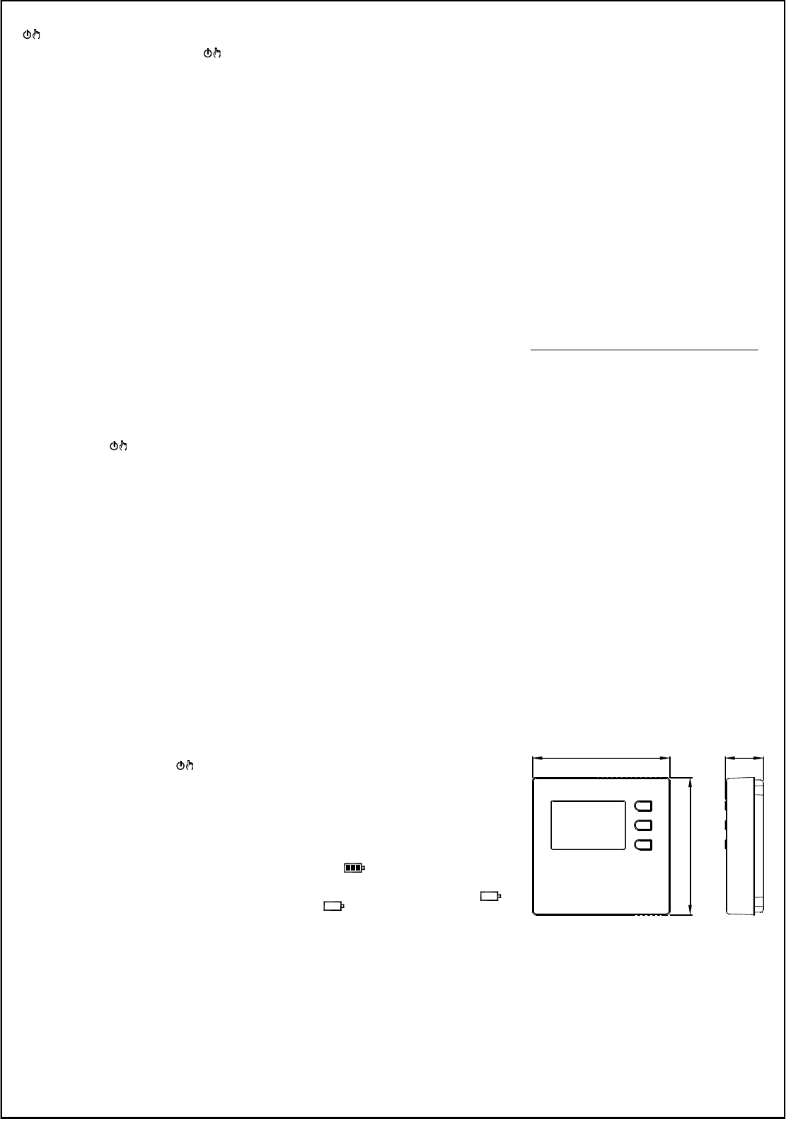
DIMENSIONS
WARRANTY
In the view of a constant developm of their products, the
manufacturer res th right for changing technical data
and featu
against any la conformity acco to the European
Directive 1999/44/EC as well as to the manufacturer’s
document about the warranty policy. The full text of w
available on request from the seller.
Width Modulation) mode.
Customisable P13
had
will
to the different r pro b a ti
and cycle time parameters.
P12: extends drive mode of output to oth
parameter is
more channel receiver (DLP ---).
If receiver
configured
P11 and r parameters from P13 to P17 hysteresis,
proportional band, additional time and cycle time. The
thermostat can, i this way, be used to co the output
drive on
and
receiver h
or make an
be driven by a simple, not configurable, thermostat.
P13:
an ON/OFF adjustment (no) is chosen in P11 .
P14: PW proportional ban it i used for proportional
adjustment when the o i configured in P11, for be
driven with PWM (YES).
P15: integrative t u proportional
adjustment when the o i configured in P11, for be
driven with PWM. The integrative action is not had if set zero.
P16:
minutes, m variable
width impulse repeated.
P17:
impulse width o switch-on tim This
parameter
event an e actuator i connected, o
switch-ons for l ope
generate significant output actions.
P18: this parameter a you to choose w to activate
the
instead of the normal display of the room temperature. If the
option is left to ‘no’, the display default shows t room
temperature,
set-point temperature will be default d
TEMPERATURE REGULATION
The thermostat can
PWM mode.
The
and, therefore, to regulate the room temperature with
maximum comfort and power saving.
However, different rooms require di settings to obtain
precise adjustment.
The parameters responsible for adjustment quality are:
- P14 Proportional band
- P15 Integration time
The proportional band in °C is the difference between set-point
and
The proportional more the
system upo
narrow proportional band setting can gener room
temperature oscill or system in An e
large
set-point, i the room. No additional action is had when the
integration time is set at zero and the adj P
(Proportional) type.
Adjustment will be of P + I (Propor + Integral) tpe by
setting
integral time the longer is the integral action, vice
integral time generates a mild integral action. A mild or
missing integral action
-point
integral action may cause the room to oscillate.
These parameters may require modifying, depending on the
room being worked on, in order to obtain the best adjustment.
DISPLAY BACK-LIGHTING
Switch-on of the display Switch- is autom after 20
seconds from last button pressure.
BATTERIES INSERTION/REPL
The
means of sy
all three level indicators inside the symbol are on.
On the contrary, the batte are drained and must be
replaced when the symbol appears completely em
The symbol
drained to allow radio transmission.
For replacement proceed as explained in 1 , 2
and 4 at page 3.
2