TM 3020-RF
Op General
Th en c for r b us to
c p e i e e t s
a
ap
s
dev to re co f ta sys co-
nents.
In
St
Remove the -•
me
Inser•
(L
pa
ri
Reattach the battery com-•
pa cove an cli in
place.
New
batter
) will
be
pr
Neve
Do
Do n
Do n
U d
regular domestic
be t
St
Th
have i
mat
Use t•
the ye
Co•
Use t•
the m
Co•
Use t•
the d
Co•
Use t•
the h
Co•
Use t•
the m
Co•
Th
co
If wit rot•
∏
”
ca
re
wil
Th•
ised T
whe
se
On•
dis
Wh
tea
bu
St
Th c b on all s hea v
Th
he
old t
T the the dial an •
clo
Re ther of t•
the
Re fro•
val
An
the c ce va Ada-
er for D va (R RAV R a inc in t
sc
vie
Th•
the va
cu
In th•
the ex
at
Th•
in ad
of th
The controller
onl be in “IN is s on th-
ing
tha ada Du
be di
Pla•
Ti•
“IN•
Th•
on th
Af•
mo
If the adju
an
to move th
1. Se
T a-
ri
i-
tur
Press and hold down the menu but
“PR•
Co•
“DA wi wh ca•
us
the wee (
day
Co•
Th•
display
In a
ever
Co•
S-•
ta
sh
Co•
Th n appe o•
the dis
Use
Co•
Then,-•
le
Kee thi unt you have fi s•
tem
After-•
pe
Co•
In
the
unt
2
Th
pe
for ea con
he
re
From 00:00 to 06:00 17.0°C
From 06:00 to 09:00 21.0°C
From 09:00 to 17:00 17.0°C
From 17:00 to 23:00 21.0°C
From 23:00 to 23:59 17.0°C
To s
for eve
ar
s l 0
fr
If
sp
Monday to Sunday
From 00:00 to 06:00 16.0°C
From 06:00 to 09:00 22.0°C
From 09:00 to 12:00 17.0°C
From 12:00 to 14:00 20.0°C
From 14:00 to 17:30 17.0°C
From 17:30 to 23:30 21.0°C
From 23:30 to 23:59 16.0°C
I
day o
Monday to Friday
From 00:00 to 08:30 17.0°C
From 08:30 to 17:00 21.0°C
From 17:00 to 23:59 17.0°C
Saturday and Sunday
From 00:00 to 23:59 15.0°C
3. O
T 3 below
pre
be s
Holiday • (
) : Se
ta
Ma• Ma ope
us
Au• Weekly-
mat
4. C
The
cess this menu,
than 3 seconds).
PRO: •
the
DA•
POS: Fo•
D•
ing t
AER For se t “ op te an tim•
so t
of ventilation
TOF: For s•
Ple rea ord
device into operation. Keep the
to it a
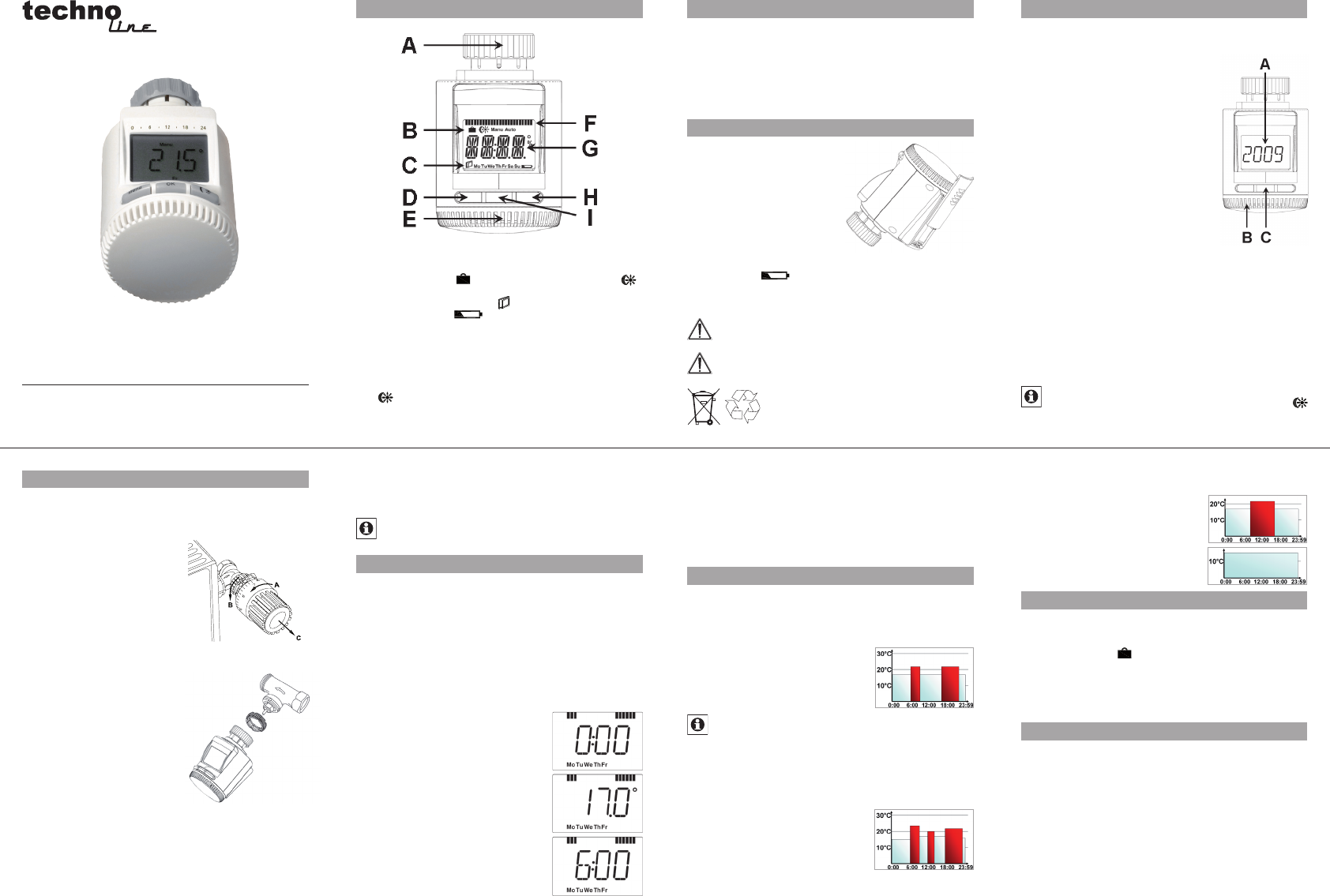
A Th
B Ho
)
maManu ), autoAuto )
C “W ope sym (
day o we “ba
em
)
D M s
3 se
E Set
F Swi
G C
items,
H
-
button:
temperatu
I OK b
5
2
6
3
7
4
8