Anschluss an CDL
Connection with CDL
braun/brown
welß/white
gelb/yellow
Lötseite / Soldering side
Stecker / Plug
MS 8100
www.sensus.com
info.de@sensus.com
info.gb@sensus.com
MS 8100 - 001 0509 • Material Number / Material nummer. 78 11 40 41
Der HRI ist in zwei Ausführungen erhältlich:
• HRI PulseUnit, als hochauflösender Impulsgeber unter
Berücksichtigung der Fließrichtung
• HRI DataUnit, wie HRI PulseUnit aber mit Datenschnittstelle,
um die Zählernummer und den Zählerstand auszulesen.
Lieferumfang
HRI Sensor, Bajonettring, Deckel mit Aussparung, 2 Schrauben, 2
Plombierhülsen für die Einschraubstellen, 1 Klebeplombe
Installation:
Unmittelbar vor der Montage des HRI ist es unbedingt
erforderlich die Aluminium-Folie auf der Unterseite zu
entfernen. Zur Montage wird ein Schraubendreher
Torx (T8) oder Schlitz (3,5*0,6) empfohlen. Das
Drehmoment sollte 0,6Nm betragen
Wasserzähler mit Kunststoffzählwerk
Zuerst den Deckel entspr. Abbildung 2 austauschen. Anschließend den
HRI mit den zwei Öffnungen an der Unterseite auf die Dome der
Zählwerkoberseite aufsetzen und mit den beiden beiliegenden
Schrauben befestigen. Zur Sicherung der Einschraubstellen je eine
Plombierhülse über den Schrauben eindrücken. Der Bajonettring und
die Klebeplombe werden nicht benötigt.
Wasserzähler mit Glas/Cu-Zählwerk
Zuerst den Deckel austauschen. Den HRI mit den beiden beiliegenden
Schrauben auf den Bajonettring montieren. Zur Sicherung der
Einschraubstellen je eine Plombierhülse über den Schrauben
eindrücken. Den Bajonettring mit dem montiertem HRI auf das
Zählwerk aufsetzen und verdrehen bis dieser in die vorgegebenen
Aussparungen eintaucht. Gleichzeitiges Drücken nach unten und
Drehen des Bajonettring gegen den Uhrzeigersinn verrastet diesen in
seiner korrekten Position. Den Rastschieber mit der beiliegenden
Klebeplombe sichern. Die Demontage des Bajonettring vom Zählwerk
erfolgt durch Anheben des Rastschiebers und Drehung im
Uhrzeigersinn.
Lieferbare Ausführungen
Der HRI kann in vier verschiedenen Impulsmodes geliefert werden
HRI PulseUnit: Typ A1, A2, A3 und A4
HRI DataUnit: Typ B1, B2, B3 und B4
mit folgende Ausgangsimpulswertigkeiten:
D = 1 / 2,5 / 5 / 10 / 25 / 50 / 100 / 250 / 500 oder 1000
**) Saldierte Impulse: Rückwärtsimpulse werden durch Unterdrücken
einer gleichen Anzahl von Vorwärtsimpulsen ausgeglichen. Das
bedeutet, keine Ausgangsimpulse während dieser Zeit trotz
Vorwärtsfluss.
Masse (braun)
DATA (grün) nur bei HRI Typ B (alternativ auch für ext.
Stromversorgung nutzbar)
Batterie oder externe Versorgung (für alle HRI-Typen):
Batterie: 3V Lithium mit mehr als 10 Jahre Lebensdauer.
Mit einer ununterbrochenen Stromversorgung 24 Volt DC (max. 50
VDC) erhöht sich die Lebensdauer auf mehr als 15 Jahre. Bei
Spg.ausfall übernimmt die Batterie des Moduls die Stromversorgung.
Damit gehen keine gespeicherten Werte verloren und das Modul setzt
die Volumenerfassung autonom fort. Die externe Stromversorgung
kann auch durch eine M-Bus Zentrale erfolgen.
Technische Daten
• Umgebungstemperaturen Lagerung: -20°C.....+65°C
Betrieb: -10°C.....+65°C
• Kabellänge: 1,5m
• Schutzklasse IP 68
• EMV Anforderungen nach EEC98/34 entspricht EN61000-6-1
Impulsausgänge (I1/I2) alle HRI-Typen
Open Collector Impulsausgabe gemäß ISO/TC30
Vmax: 24V / Imax: 20mA/ Pmax: 0,48VA/ fmax: 5Hz
Max. Spg. bei geschlossenem Schalter: 0,3V + I * 250Ω
Wenn das Dateninterface nicht genutzt wird kann durch
Zusammenschluss von braunem und grünem Draht der
Serienwiderstand auf 150Ω verringert werden.
Impulsbreite fest 124ms,
Durchflussrichtung (A3/B3): Signal I2 ist gegenüber l1 um 18μs
vorauseilend.
zulässige Kabelverlängerung max. 10 m
Außerhalb geschlossener Gebäude wird ein Überspannungsschutz
empfohlen.
Daten-Schnittstelle (nur HRI-Bx)
M-Bus und MiniBus (Auto speed detection: 300/2400 Baud)
Protokoll gemäß EN13757-3 entspricht IEC 870 / EN 1434
Daten: Zählernummer und Zählerstand (wahlweise 1 l oder 1 m
3
Auflösung)
Kabelverlängerung: gemäß M-Bus Spezifikation
Bei MiniBus Anwendung max. 50m bei einer verdrillten 2-Drahtleitung
min 0,25mm2
Die Anzahl von Auslesungen bei M-Bus ist unbeschränkt, bei MiniBus
nicht öfters als 5 mal täglich, damit die Batterielebensdauer von 10
Jahren nicht unterschritten wird.
Die Anzahl von Auslesungen ist unbeschränkt.
Mit der Datenschnittstelle lassen sich mit Hilfe der MiniCom (Version
>3.0) folgende Werte einstellen (Standardeinstellung ab Werk in
Klammern):
Primäradresse (0), Sekundäradresse (Fab.Nr. des HRI)
ZählerNr. (Fab.Nr. des HRI)
Zählerstand (0); wenn Aluminium Folie fehlt, kann der Zählerstand <>
0 sein.
Impulsmode (je nach Bestellung), Impulswertigkeit (je nach Bestellung)
Achtung: die Auflösung des Zählerstandes (1 l oder 1 m
3
) lässt sich
nicht ver-ändern. Diese Einstellung muss bei der Bestellung korrekt
angegeben werden.
Wird der HRI als Ausführung auf einen Zähler montiert bestellt, werden
ab Werk die Sekundäradresse, ZählerNr. und Zählerstand mit der des
montierten Zählers vorbesetzt. Eine Einstellung ist damit nicht mehr
notwendig.
Bei gleichzeitiger Nutzung der Datenschnittstelle und Impulsausgang
ist auf Potentialfreiheit der angeschlossenen Geräte zu achten.
Während der Kommunikation sind je nach Eingangsbeschaltung des
Impulssammlers Impulsverluste möglich.
Entsorgungshinweise
Dieses Produkt enthält eine Lithiumbatterie und soll zum Schutz
unserer Umwelt nach Ablauf der Verwendungsdauer nicht im Hausmüll
entsorgt werden. Die Entsorgung kann über ein Sensus Metering
Systems Service Center erfolgen. Sollten Sie die Entsorgung dennoch
selbst übernehmen, beachten Sie die örtlichen und nationalen
Bestimmungen zum Umweltschutz.
1
2
3
EINBAU- UND BETRIEBSANWEISUNG - HRI INSTALLATION AND OPERATING INSTRUCTIONS - HRI
HRI is available in two versions.
• The HRI PulseUnit provides high-resolution pulse outputs.
• The HRI DataUnit has additionally a data interface for reading meter
id-number and index.
Delivery parts
HRI sensor, Bayonet ring, Cut Meter lid, 2 screws, 2 screw seals 1
adhesive seal
Installation:
Just before mounting the HRI on the meter it
is essential to remove the aluminum foil at the
bottom side. A screwdriver Torx (T8) or Slot (3.5*0.6) is
recommended for mounting. The torque should be 0.6Nm
Meters with plastic register
Change the lids and put the HRI on the meter, so that the two pins on
top of the register fit exactly into the holes at the bottom of the HRI. Fit
the two screws. For tamper protection fit the plastic seals on top of the
screws. The bayonet ring and the adhesive seal are not used for this
register type.
Meter with glass-copper register
First exchange the lids. Mount the HRI with both the screws on the
bayonet ring. For tamper protection fit the plastic seals on the top of
the screws. Fit the bayonet ring with the mounted HRI on the top of the
meter register and turn it until it is drops into place. Push and turn the
bayonet ring clockwise until the lever clicks into place. If required fit the
adhesive seal. To remove the HRI lift the lever and rotate
anticlockwise.
Type
Depending on the order specification, HRI can be delivered in four
different pulse modes
HRI Pulse Unit: Type A1, A2, A3 and A4
HRI Data Unit: Type B1, B2, B3 and B4
with following pulse weights:
Possible values for residential meters:
D = 1 / 2,5 / 5 / 10 / 25 / 50 / 100 / 250 / 500 or 1000
**) Balanced pulses: Reverse flow must be compensated by identical
forward flow before more pulses are output. That means, no output
pulses during this period even the meter is counting forward.
Ground (brown)
DATA (green) only for HRI Type B (alternatively for external power
supply)
Battery or external power supply (for all types):
Battery 3V Lithium with autonomy lifetime more than 10 years.
With unbroken permanent power supply of 24VDC (max. 50VDC) unit
lifetime is increased by more than 15 years. In case of external power
failure the battery of the module takes over the supply. All stored data
are retained and the volume detection continuous autonomously. The
external power supply can also be an M-Bus central unit.
Technical data
• Temperature range Storage: -20° to +65° C
Operation: -10° to +65° C
• Cable length: 1,5 m
• Hermetically-sealed housing IP 68
• EMC acc. EEC directive 98/34 equal European standards
EN61000-6-1
Pulse-outputs (I1/I2) all types:
Open drain transistor switch according ISO/TC30
Vmax: 24V / Imax: 20mA/ Pmax: 0,48VA/ fmax: 5Hz
Max. voltage by closed switch: 0.3V + I * 250Ω
If the data interface isn’t used the serial resistance can be reduced by
150Ω with the connection of green and brown wire.
Pulse length 124ms fixed,
Flow direction (A3/B3) signal l2 is 18μs prior to I1
Operational cable length up to 10m
Transient voltage protection is highly recommended for wiring outside
buildings.
Data interface (HRI-Bx only)
M-Bus and MiniBus (Auto speed detection: 300/2400 Baud)
Protocol according EN13757-3 equal IEC 870 / EN 1434-3
Data: meter id-no., meter index (optional 1 litre or 1 m
3
resolution)
Operational cable length: according to M-Bus specification.
With MBus the account of reading is unlimited, with MiniBus the
reading shouldn’t be more than 5 times per day to avoid battery
lifetime less than 10 years.
With the data interface following values can be set via MiniCom
(version >3.0); standard setting from the factory in brackets:
Operational cable length: according to M-Bus specification.
With MBus the account of reading is unlimited, with MiniBus the
reading shouldn’t be more than 5 times per day to avoid battery
lifetime less than 10 years.
Primary address (0), Secondary address (HRI-Fabrication No.)
Meter id-no. (HRI-Fabrication No.)
Meter index (0); if the aluminium foil is missing, index can be different
Pulse mode (according the order), Pulse weight (according the order)
Attention: resolution of meter index can’t be changed, so this setting
must be correctly defined with the order.
If the HRI is ordered mounted on top of a meter , the secondary
address, meter id-no. and meter index are preset with the meter’s
values. Setting on site isn’t necessary.
If data interface and pulse output is used at the same time, potential
free connection for the connected devices are requested. During data
communication pulse lost is possible depending on the pulse
collector’s input circuit.
Disposal instructions
This product contains a lithium battery and to protect the environment
should not be disposed in household rubbish when its serviceable life
is over. Disposal can take place through a Sensus Metering Systems
Service Centre. If however you want to take care of the disposal
yourself, please comply with the local and national regulations for
environmental protection.
1
2
3
4
4
!
!
1
2
3
4
5
6
1
3
2
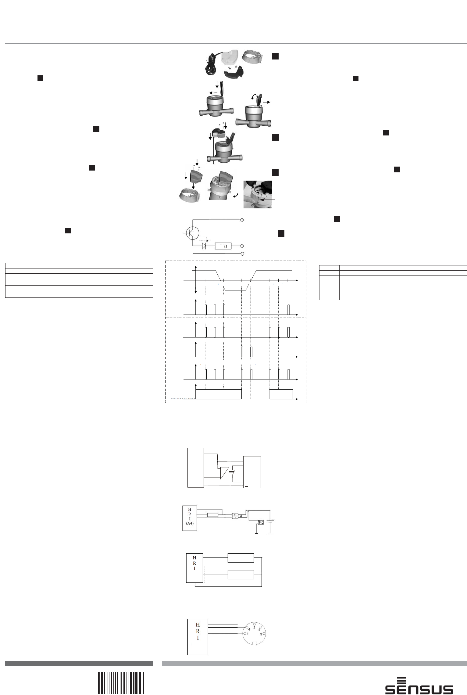
Pulse mode
Lines A1/B1 A2/B2 A3/B3 A4/B4
l1
(white)
Balanced pulses**
Forward flow
pulses
For/back-ward
pulses
Balanced pulses**
l2
(yellow)
Not used
Reverse flow
pulses
Flow direction
Tamper/ Error
"normally close"
I1: weiß/white
oder/or
I2 : gelb/yellow
Masse/Ground
braun/brown
4
Data: grün/green
1kΩ
grün/green
welß/white
braun/brown
+24V
88888888
88888888
TR100 (829372)
Fernanzeige/Remote display
welß/white
gelb/yellow
braun/brown
Rückwärts/Backward
nur mit A2/B2 only with A2/B2
0V
0V
count 20Hz
count 20Hz
Vorwärts/Forward
Diese Anwendung kann auch als Testwerkzeug für alle HRI Typen verwendet werden
This application can be also used as a test tool for all HRI types
Impulsmode
Leitung A1/B1 A2/B2 A3/B3 A4/B4
l1
(weiß)
Saldierte
Impulse**
Vorwärts-impulse
Vor-/Rück-
wärtsimpulse
Saldierte
Impulse**
l2
(gelb)
nicht verwendet Rückwärts-impulse Fließrichtung
Fehler, wenn
offen
Anshlussbeispiele/Application examples:
Alle Anschlüsse mit Versorgung sind optional. Es kann auch die interne
baterie des HRI als Spg. versorgung verwendet werden
All connections with ext. power supply are optional. It can be use the
HRI’s internal battery.
welss/white
braun/brown
grün/green
+24V
SPS mit geschalteter Spg.versorgung
PLC with switched power supply
SPS mit geschalteter Masse / PLC with switched ground
HRI fremdgespeist / PLC with external power supply
vorwärts / forward
vorwärts /
forward
I2 (Richtung / Direction)
rückwärts / backward
t
t
I1 (vortwärts & rückwärts / forwards & backwards)
t
1 2 3 4 5 6 7 8
Mode A3 / B3
I2 (rückwärts / backwards)
1 2
t
I1 (vorwärts / forward)
1 2 3 4 5 6
Mode A2 / B2
geschlossen / close
offen / open
Mode A1 / B1
1 2 3 4
t
I1 (saldierend / balanced)
rückwärts / backwards
Zählerstand
meter index
vorwärts / forward
Durchfluss / Flow
t
..01 ..02 ..03 ..02 ..01 ..02 ..03 ..04
Material Nr. 78114041
geschlossen / close
offen / open
geschlossen / close
offen / open
geschlossen / close
offen / open
geschlossen / close
offen / open
250
0,3V
(A3)
HRI
A4
SPS
(PLC)
puls input
(A2/B2)