Electrical Connection
Elektrischer Anschluß / Connexions électriques
Elektrische aansluitingen
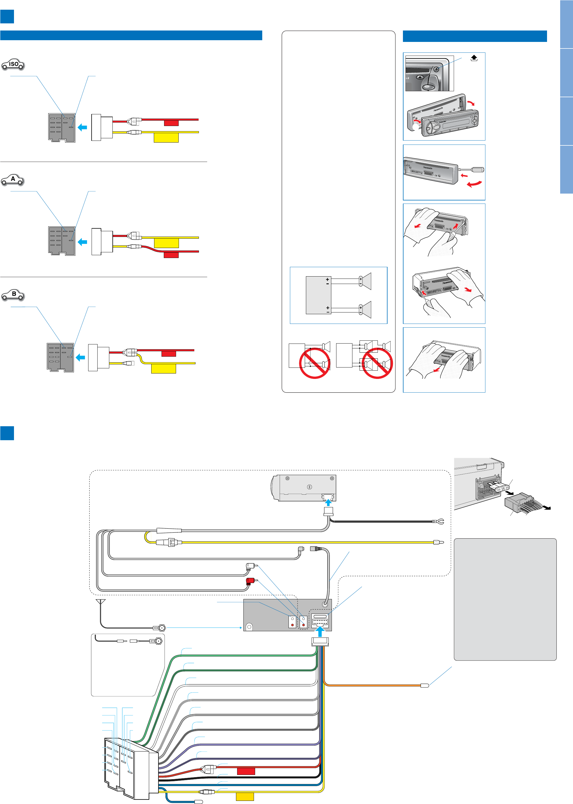
Wiring Diagram
Verdrahtungsplan
Schéma de connexions électriques
Bedradingschema
CD Changer / CD-Wechsler
Changeur de CD / CD-wisselaar
Extension Cord / Verlängerungskabel
Cordon d’extension / Verlengsnoer
Fuse (3 A) / Sicherung (3 A)
Fusible (3 A) / Zekering (3 A)
RCA Cord / Cinch-Kabel / Cordon RCA / RCA (tulp) snoer
Antenna
Antenne
Antenne
Antenne
B7 : Rear Left +/Hinten Links +
Arrière gauche +/Links achter +
B8 : Rear Left –/Hinten Links –
Arrière gauche –/Links achter –
B5 : Front Left +/Vorne Links +
Avant gauche +/Links voor +
B6 : Front Left –/Vorne Links –
Avant gauche –/Links voor –
B3 :
Front Right +
/Vorne Rechts +
Avant droit +
/Rechts voor +
B4 :
Front Right
–/Vorne Rechts –
Avant droit
–/Rechts voor –
B1 :
Rear Right +
/Hinten Rechts +
Arrière droit +
/Rechts achter +
B2 :
Rear Right
–/Hinten Rechts –
Arrière droit
–/Rechts achter –
Preamp Out Connector (Rear)
Vorverstärker-Ansgangsbuchse (Hinten)
Prises de sortie à Préampli (Arrière)
Uitgangsaansluiting voorversterker (Achter)
CD Changer Control Connector
CD Wechsler Steuerbuchse
Connecteur de commande de chargeur de CD
Stekker CD-wisselaar bediening
Changer Control DIN Cord / CD-Wechsler DIN-Steuerkabel
Cordon DIN de commande de changeur / DIN snoer wisselaar bediening
Battery Lead (12 V DC) / Batteriekabel (12 V DC)
Fil de batterie / Accusnoer (12 V gelijkstroom)
Ground Lead / Massekabel
Fil de mise à la masse / Aarding
Fuse (15 A)
Sicherung (15 A)
Fusible (15 A)
Zekering (15 A)
Ground Lead
To a clean, bare metallic part of the car
chassis.
Massekabel
An ein sauberes, metallisches Teil des
Fahrzeugchassis.
Fil de mise à la masse
A une partie métallique propre découverte
du châssis de voiture
Aarding
Naar een schoon, bloot metalen onderdeel
van het chassis.
A8 :
Power Lead (ACC or IGN)
To ACC power, +12V DC.
Versorgungskabel (ACC oder IGN)
An die ACC-Stromklemme, +12 V
Gleichspannung
Fil d’alimentation (ACC ou IGN)
A l’alimentation ACC, +12V CC
Stroomdraad (ACC of IGN)
Naar ACC stroomvoorziening, + 12 V
gelijkstroom.
A7 :
Battery Lead
To the car battery, continuous +12 V DC.
Batteriekabel
An die Batterie des Fahrzeuges, kontinuierlich +12
V Gleichspannung.
Fil de batterie
A la batterie de voiture, alimentation continue de
+12 V CC
Accudraad
Naar de accu van de auto, doorlopende
stroomvoorziening + 12 V gelijkstroom.
A4 :
Motor Antenna Relay Control Lead
To Motor Antenna. (Max. 500 mA) (This
lead is not intended for use with a switch
actuated power antenna)
Amp·Relay Control Power Lead
To Panasonic power amplifier (synchronized with the
power on/off of amplifier).
Steuerkabel für Relais der motorbe-
triebenen Antenne (Zu motorbetriebenen
Antenne) (max. 500 mA)Dieses Kabel
dient nicht für die Verwendung mit einer
über einen Schalter aktivierten motorbe-
triebenen Antenne.
Verstärker/Relais-Steuerstromleiter
An den Panasonic Leistungsverstärker (synchronisiert
mit der Ein/Ausschaltung des Verstärkers).
Fil de commande de relais d’antenne
motorisée
A l’antenne motorisée (500 mA maxi.)(Ce
fil n’est pas conçu pour l’usage avec l’an-
tenne commandée par interrupteur.)
Cordon d’alimentation de la commande
de relais d’amplificateur
A l’amplificateur de puissance de Panasonic (synchro-
nisé à la mise sous/hors tension de l’amplificateur)
Stuurdraad relais gemotoriseerde
antenne
Naar de gemotoriseerde antenne. (Max.
500 mA) (Deze draad is niet bedoeld voor
een gemotoriseerde antenne die met een
schakelaar wordt ingeschakeld.)
Stuurstroomdraad versterker relais
Naar de Panasonic eindversterker. (Gesynchroniseerd
met het in-/uitschekelen van de stroom voor de ver-
sterker.)
A5 :
Telephone Mute Lead
To mute lead of car telephone (mute activated while using
telephone).
Navi Mute Lead
To mute lead of navigation system (mute activated during
voice guidance).
Telefon-Stummschaltungskabel
An das Autotelefon-Stummschaltungskabel (Stumm-
schaltung bei Benutzung des Telefons aktiviert).
Navigations-Stummschaltungskabel
An das Navigations-Stummschaltungskabel (Stummschaltung
während akustischer Ansagen aktiviert).
Fil d’assourdissement pour téléphone
Au fil d’assourdissement du téléphone pour voiture
(assourdissement activé en cas d’utilisation du téléphone)
Fil d’assourdissement pour Navi
Au fil d’assourdissement du système de navigation (assour-
dissement activé pendant le guidage vocal)
Telefoon-dempingsdraad
Naar de dempingsaansluiting van de autotelefoon.
(Geluidsweergave gedempt wanneer de telefoon wordt
gebruikt.)
Navigatiesysteem-dempingsdraad.
(Geluidsweergave gedempt tijdens stembegeleiding.)
C1 :
e Power Connector / Versorgungsstecker
Connecteur d’alimentation /
Stroomstekker
e Power Connector
Versorgungsstecker
Connecteur d’alimentation
Stroomstekker
If the fuse (rear panel) blows frequently,
there may be something wrong with the unit
or wiring connection. Consult your nearest
Panasonic Service Center for service.
Falls die Sicherung (Rückwand) häufig
durchbrennt, liegt wahrscheinlich ein
Problem an Ihrem Gerät oder an den
Drahtanschlüssen vor. Wenden Sie sich an
den nächsten Panasonic Kundendienst.
Le grillage fréquent du fusible (à l’intérieur
du panneau arrière) témoigne souvent d’une
défaillance de l’appareil ou d’une mauvaise
connexion de fils. Dans tel cas, prenez con-
tact avec le centre de service après-vente de
Panasonic le plus proche.
Als de zekering (op het achterpaneel) regel-
matig doorbrandt, is er misschien iets mis
met het toestel of de bedrading. Vraag uw
dichtstbijzijnde Panasonic Service-centrum
om inspectie of reparatie.
CD Receiver / CD-Spieler/Receiver/
Récepteur de CD / CD Receiver
CQ-RDP162/RDP112N
CQ-RDP152/RDP142/RDP102N
(Only for CQ-RDP162/RDP112N)
(Nur für CQ-RDP162/RDP112N)
(Seulement pour CQ-RDP162/RDP112N)
(Alleen voor CQ-RDP162/RDP112N)
CX-DP88N
(Option/Option/option/los verkrijgbaar)
Fuse (15 A)
Sicherung (15 A)
Fusible (15 A)
Zekering (15 A)
Fuse Replacement
Austauschen der Sicherung
Remplacement du fusible
Vervangen van de zekering
4
There might be slight differences in colors of cords between the drawing below and the actual cords.
Es kann ein geringer Unterschied in der Farbe der Kabel zwischen der nachfolgenden Zeichnung und den
tatsächlichen Kabeln auftreten.
Les couleurs de cordons illustrés sur le schéma peuvent différer plus ou moins de celles de cordons réels.
Er kan een klein kleurverschil bestaan tussen de kleuren van de bedrading in de onderstaande afbeelding en in
werkelijkheid.
You need to purchase a connector
(option) for this type of antenna plug.
Sie müssen einen Zwischenstecker
(Option) für diesen Typ von
Antennenstecker kaufen.
Il est nécessaire d’acheter un
connecteur (option) pour ce type de
prise d’antenne.
U dient voor dit type
antennestekker een adapter (los
verkrijgbaar) aan te schaffen.
EnglishDeutschFrançaisNederlands