741476
1
Zoom out
Zoom in
Previous page
1/2
Next page
TC4F00131
Rivelatore infrarosso con microcamera
a colori Day&Night -TI14
Infrared Detector with colour Day&Night
microcamera -TI14
ELKRON S.p.A.
Via Cimarosa, 39 – 10154 Torino (TO) – Italy
TEL.+39.011.3986711–FAX +39.011.3986790
www.elkron.com – mail to: info@elkron.it
ITALIANO
CARATTERISTICHE TECNICHE
Tensione nomin. di alimentazione rivelatore...............12 V—
Tensione di funz. min – max rivelatore ....................... 10 ÷14 V—
Assorbimento a 12 V— (solo rivelatore) ..................... 10.5mA nom. ; 13mA max.
Assorbimento a 12 V— (rivelatore+microcamera)......85mA nom. ; 100mA max.
Conteggio impulsi.......................................................x1 / x2
Portata lente volumetrica............................................15m (Dip SENS in OFF) – 12m (Dip SENS in ON) nominali
Copertura IR...............................................................108° (lente volumetrica – di serie)
Zone sensibili..............................................................31 su 4 piani (lente volumetrica – di serie)
Relè di allarme............................................................ relè stato solido - NC 0.1A@24V— / R max = 35
Compensazione termica.............................................Bidirezionale
Tamper antimanomissione .........................................50 mA @ 24V—
Temperatura di funzionamento................................... -10°C ÷ +50°C
Temperatura di stoccaggio ......................................... -20°C ÷ +60°C
Umidità .......................................................................Inferiore a 80%
Dimensioni esterne involucro (h x l x p)......................124 x 70 x 54 ±2mm
Peso ........................................................................... 141g
CARATTERISTICHE TECNICHE MICROCAMERA
Immagine dispositivo .................................................. 1/3" SONY Super HAD CCD II
Sistema di scansione.................................................. 2:1 Interlacciato
Frequenza di scansione..............................................NTSC : 15,734 KHz(H), 59,94 Hz(V)
Risoluzione orizzontale............................................... 550 TVL
Pixel totali ................................................................... NTSC : 811(H) x 508(V) / PAL : 795(H) x 596(V)
Pixel effettivi ............................................................... NTSC : 768(H) x 494(V) / PAL : 752(H) x 582(V)
Rapporto segnale rumore...........................................Superiore a 45dB (AGC Off)
Illuminazione minima..................................................0,05 Lux / Faceplate
Sistema di sincronizzazione ....................................... Interno
Correzione gamma ..................................................... 0,45
Uscita Video ............................................................... 1,0 Vp-p Composito (75)
Obiettivo ..................................................................... Pinhole – Focale 4,3mm (F2,0) – Apertura angolare 78°
Otturatore elettronico..................................................NTSC:1/60 ~ 1/100.000 sec/PAL:1/50 ~ 1/100.000 sec
Alimentazione esterna microcamera ..........................12 V— ( ±10% )
Consumo @ 12 V—....................................................Max. 90mA
AVVERTENZE
- Installare il rivelatore su superfici rigide, prive di vibrazioni, ad una altezza compresa tra 2 e 2,2m facendo riferimento ai
diagrammi di rivelazione in modo tale che il rivelatore rilevi spostamenti che incrociano la zona protetta.
- Nel caso di installazioni ad altezze superiori ai 2,2m si consiglia di verificare la copertura delle zone da sorvegliare.
Se necessario, intervenire regolando l’orientamento del rivelatore, se montato sullo snodo o regolando il pcb.
- Evitare il posizionamento del rivelatore vicino a fonti di calore o alla luce diretta del sole. L’orientamento diretto
della telecamerina verso sole, riflettori lenticolari o oggetti foto riflettenti può distorcere le immagini.
- Evitare che esistano, a causa di mobili, etc. zone cieche nell’area protetta entro cui possa muoversi l’intruso.
- Evitare la presenza di animali nell’area protetta. E’ consigliabile utilizzare per i collegamenti un cavo schermato e
preferibilmente un cavo per ogni rivelatore. Si possono collegare più sensori nello stesso ambiente senza problemi
di interferenze. Non toccare con le dita la superficie speculare del piroelettrico; nel caso, pulire con cotone ed un
po’ di alcol. Separare per quanto possibile i conduttori dell’impianto di allarme da quelli della rete principale.
- Per evitare l’ingresso di insetti all’interno del rivelatore, è consigliabile coprire eventuali eccedenze dei fori praticati
sul fondo con della spugna adesiva. Non installare il rivelatore all’esterno, alla pioggia o in ambienti con alto tasso
di umidità.
- È consigliabile utilizzare la telecamera insieme ad un monitor dotato di livello standard di impedenza di entrata
video pari a 75 .
- Non tentare di smontare la telecamera: i componenti interni non sono riparabili dall’utente. Per tutti gli interventi
rivolgersi sempre a personale qualificato.
INSTALLAZIONE SENZA SNODO
Per rimuovere il coperchio del rivelatore togliere la vite di chiusura (se inserita) e premere sul dente di fissaggio.
Per togliere il circuito stampato estrarre la vite “I(Fig. 3) e fare leva sul gancetto “F(Fig. 1) .
(
Fig. 1
) A
=
PREDISPOSIZIONI PER IL FISSAGGIO AD ANGOLO
B/B1
=
PREDISPOSIZIONI A SFONDAMENTO PER IL PASSAGGIO CAVI
C
=
PREDISPOSIZIONI PER IL FISSAGGIO SU SUPERFICIE PIANA
INSTALLAZIONE CON SNODO
E’ disponibile in opzione uno snodo (SP7500111) per installazione a muro o a soffitto con kit tamper (KT7800111) e passaggio
cavi all’interno: per l’uso consultare le istruzioni specifiche. Per il montaggio dello snodo, aprire l’apposita predisposizione a
sfondamento
“D”
ed assemblare lo snodo come indicato nelle istruzioni dello stesso. Terminato l’orientamento, volendo bloccare
ulteriormente il movimento dello snodo è possibile utilizzare la vite fornita a corredo, serrando a fondo in una delle sedi
“E”
.
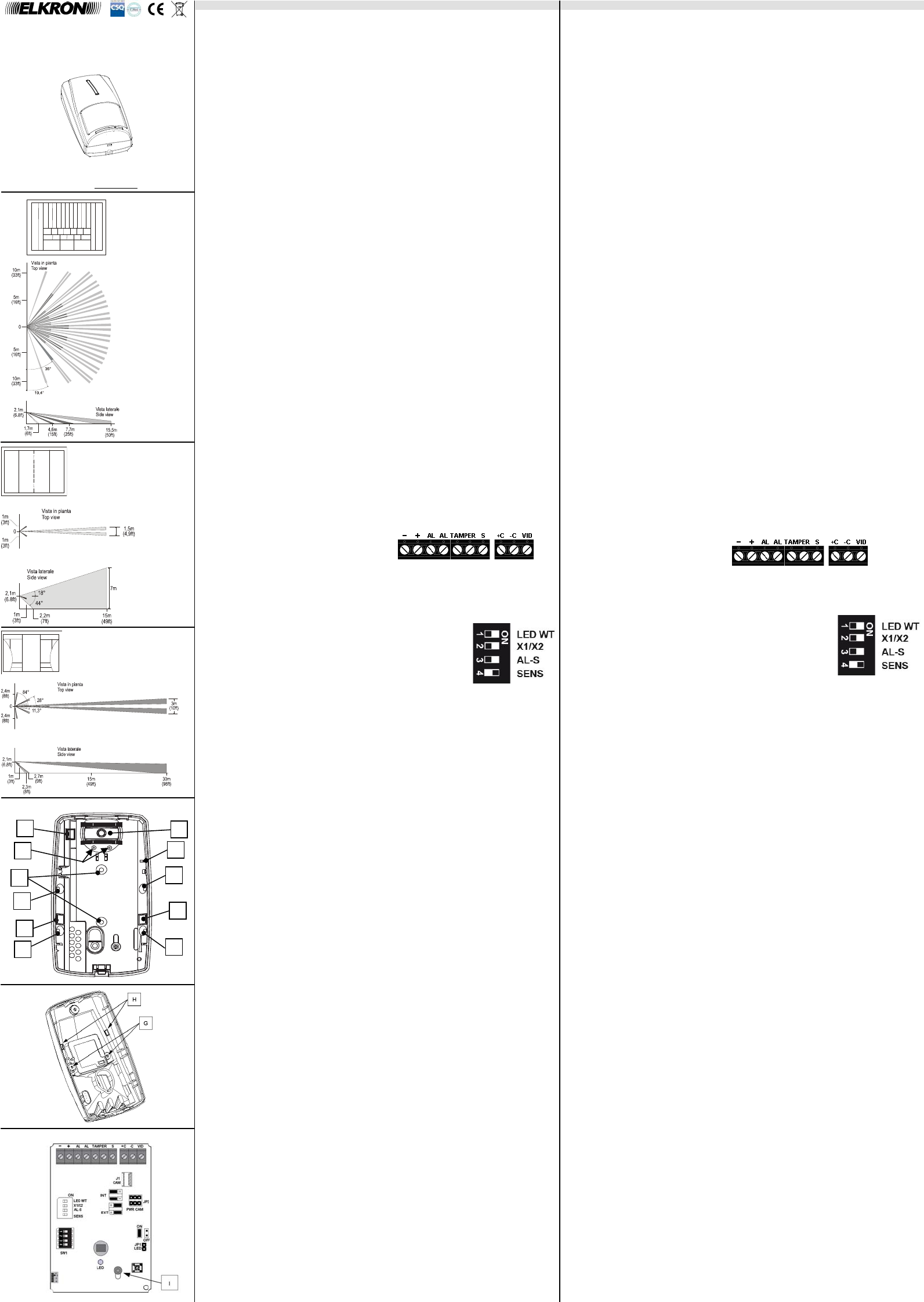
DESCRIZIONE MORSETTIERA
- Negativo di alimentazione rivelatore
+ Positivo di alimentazione rivelatore
AL Contatto NC del relè di allarme
TAMPER Contatto NC tamper
S Ingresso S
+C Positivo di alimentazione esterna microcamera
-C Negativo di alimentazione esterna microcamera
VID Uscita video
DESCRIZIONE DIP-SWITCHES
DIP1 LED WT VISUALIZZAZIONE WALK TEST OFF: ABILITATA (Default)
ON: DISABILITATA
DIP2 X1/X2 CONTEGGIO IMPULSI OFF: CONTEGGIO X1 (Default)
ON: CONTEGGIO X2
DIP3 AL-S BLOCCO USCITA ALLARME OFF: NON BLOCCATA (Default)
IN STAND BY ON: BLOCCATA
DIP4 SENS PORTATA RIVELATORE OFF: 15m
ON: 12m (Default)
PROGRAMMAZIONE RIVELATORE
INGRESSO S
S” è un comando generato dalla centrale antintrusione per informare il rivelatore sullo stato dell’impianto (attivato o
disattivato). Grazie ad esso, quando l’impianto è disattivo, sono visualizzatela memoria di allarme e di guasto. Se
non si connette questo ingresso alla centrale, il morsetto “S” va lasciato libero ed il rivelatore opera sempre come ad
impianto attivo.
- Ad impianto disattivo sul morsetto “S” del rivelatore dovrà essere presente una tensione di 12V—
- Ad impianto attivo sul morsetto “S” del rivelatore dovrà essere presente una tensione di 0V oppure lasciato“volante”
Attenzione: nel caso in cui la centrale a cui è connesso il rivelatore non disponga di un comando associato
allo stato dell’impianto, non connettere “S”.
VISUALIZZAZIONE GUASTO
Il rivelatore è in grado di rilevare situazioni di guasto della sezione infrarosso, visualizzandole tramite il lampeggio del
LED (indipendentemente dallo stato dell’ingresso “S” e del DIP LED WT, sempre se JP1=chiuso). Una condizione di
guasto provoca l’attivazione dell’uscita di allarme per tutta la durata dell’anomalia, indipendentemente dallo stato
dell’ingresso “S” e dalla posizione del DIP AL-S.
MEMORIA DI ALLARME E DI GUASTO MASCHERATA
Qualora si colleghi l’ingresso “S”, con la disattivazione dell’impianto si ha la visualizzazione della memoria di allarme
(LED acceso fisso in caso di allarme rivelato) e della memoria di guasto (lampeggio lento del LED e attivazione
dell’uscita di allarme in caso di guasto rivelato).
NOTA: Le memorie vengono resettate alla successiva attivazione dell’impianto. In caso di memoria di
guasto, la segnalazione è attiva finché il guasto permane.
ABILITAZIONE LED
Con JP1 chiuso (LED abilitato) si ha una accensione del LED per ogni rivelazione di allarme (ad impianto attivo) o di
guasto del rivelatore (indipendentemente dallo stato impianto) e per segnalare una memoria di allarme o di guasto.
Con JP1 aperto il LED è escluso e non fornisce alcuna segnalazione di allarme, di memoria o di guasto.
CONTEGGIO IMPULSI
La modalità di rivelazione è selezionabile tramite DIP X1/X2:
DIP X1/X2 OFF: per generare un allarme è sufficiente una sola rivelazione (single edge)
DIP X1/X2 ON: per generare un allarme occorreranno 2 rivelazioni (dual edge)
PRIMA ALIMENTAZIONE
Alla prima alimentazione il LED del rivelatore lampeggia per circa 30 secondi e successivamente si accende fisso
per circa 20 secondi. Durante questa fase il rivelatore non è operativo. Lo stato di normale funzionamento si avrà
allo spegnimento del LED.
PROVA PORTATA
Per effettuare la prova portata (WALK TEST), attraversare l’area protetta dal rivelatore: ogni rivelazione sarà
segnalata dall’accensione fissa del LED. Tramite il DIP LED WT è possibile disabilitare la segnalazione.
E’ necessario che JP1 sia inserito per poter abilitare il LED.
FUNZIONE PRE-ALLARME
Con il movimento di un intruso entro l’area protetta, l’avvicinamento alla soglia di allarme viene indicata visivamente
col lampeggio del LED. Questa funzione è attiva quando sul morsetto “S” è presente una tensione di 0V oppure è
“volante”. Il DIP LED WT deve essere in posizione OFF.
INCLINAZIONE DEI RAGGI SENSIBILI
Per installazioni ad altezze diverse da 2,1 metri, è possibile regolare la posizione del sensore piroelettrico rispetto
alla lente attraverso l’asola della vite di fissaggio “I” del circuito stampato. La regolazione avviene traslando il circuito
stampato verso l’alto o verso il basso, riferendosi alle tacche riportate a fianco dell’asola:
- spostando il circuito stampato verso la posizione “-4” i raggi delle zone sensibili si avvicinano;
- spostando il circuito stampato verso la posizione “+1” i raggi delle zone sensibili si allontanano.
Per permettere lo slittamento dell’elettronica è necessario fratturare il piolino ”I” di fermo che blocca l’elettronica nella
posizione standard “0”.
ALIMENTAZIONE MICROCAMERA
Configurando JP2 in modo opportuno è possibile decidere se alimentare la microcamera direttamente tramite
l’alimentazione interna del sensore oppure tramite alimentazione esterna isolando galvanicamente la connessione
video da quella del rivelatore.
Alimentazione interna per microcamera
Inserire i due ponticelli di cortocircuito come da posizione INT indicata sulla serigrafia. In questo caso utilizzare
come riferimento di massa dell’uscita video (VID) il morsetto negativo di alimentazione del rivelatore (-).
Alimentazione esterna per microcamera (Default)
Inserire i due ponticelli di cortocircuito come da posizione EXT indicata sulla serigrafia. In questo caso il negativo
della tensione di alimentazione esterna andrà collegata al morsetto –C mentre il positivo di alimentazione andrà
collegata al morsetto +C. ATTENZIONE: si raccomanda di utilizzare una tensione stabilizzata a 12V
(±10%),
che garantisce immagini di qualità ottimale.
SOSTITUZIONE DELLA LENTE
Nel caso di sostituzione della lente ( lente a tenda oppure lente a lungo raggio ) per accedere alla lente occorre:
rimuovere la microcamera agendo sulle viti “G(Fig. 2)
premere sui denti di fissaggio “H per estrarre la parte anteriore del coperchio con annessa la lente
sostituire la lente facendo attenzione che la scritta “Fresnel” sia rivolta verso il basso e la parte liscia verso
l’esterno. Riposizionarne la parte anteriore del coperchio nell’apposita sede, rimontare la microcamera
riavvitando le viti del supporto nelle sedi “G”.
ACCESSORI OPZIONALI
- Snodo SPA10 (10 snodi per IRA-IMA) - SP7500111
- KIT 10 Tamper per SPA10 - KT7800111
- KIT 2 lenti VB (tenda) 1.2 GI V1 - LT1310111
- KIT 2 lenti LR (lungo raggio) 1.2 GI 12V1 - LT1410111
ENGLISH
TECHNICAL SPECIFICATIONS
Detector nom. supply voltage..................................... 12 V—
Detector min/max oper. Voltage................................. 10 ÷14 V—
Absorption 12V— (detector only) ............................... 10.5mA nom. ; 13mA max.
Absorption 12V— (detector+microcamera)................ 85mA nom. ; 100mA max.
Pulse count ................................................................ x1 / x2
Volumetric lens capacity............................................. 15m (Dip SENS in OFF) – 12m (Dip SENS in ON) nominal
IR Covering ................................................................ 108° (Volumetric lens – serial)
Sensitive area............................................................. 31 on 4 planes (Volumetric lens – serial)l
Allarm relay ................................................................ solid state relay - NC 0.1A@24V— / R max = 35
Thermal compensation............................................... Bi-directional
Anti-tamper device ..................................................... 50 mA @ 24V—
Operating temperature ............................................... -10°C ÷ +50°C
Storage temperature .................................................. -20°C ÷ +60°C
Humidity ..................................................................... Less than 80%
Dimensions of external casing (H x L x D) ................. 124 x 70 x 54 ±2mm
Weight ..................................................................... 141g
MICROCAMERA TECHNICAL SPECIFICATIONS
Device Image ............................................................ 1/3" SONY Super HAD CCD II
Scanning system........................................................ 2:1 Interlaced
Scanning frequency.................................................... NTSC : 15,734 KHz(H), 59.94 Hz(V)
Horizontal resolution................................................... 550 TVL
Total pixels ................................................................. NTSC : 811(H) x 508(V) / PAL : 795(H) x 596(V)
Effective Pixels........................................................... NTSC : 768(H) x 494(V) / PAL : 752(H) x 582(V)
Signal to noise ratio.................................................... Greater than 45dB (AGC Off)
Minimum lighting ....................................................... 0.05 Lux / Faceplate
Synchronisation system ............................................. Internal
Gamma correction...................................................... 0.45
Video output ............................................................... 1.0 Vp-p Composite (75)
Objective .................................................................... Pinhole – Focal 4.3mm (F2.0) –Angular aperture 78°
Electronic shutter........................................................ NTSC:1/60 ~ 1/100,000 sec/PAL:1/50 ~ 1/100,000 sec
Microcamera external power supply........................... 12 V— ( ±10% )
Consumption @ 12 V— ............................................. Max. 90mA
WARNING
- Place the detector on hard surfaces, free from vibrations at a height between 2 and 2.2 metres (6.5 and 7.2 ft).
Refer to standard detection diagrams, so that the detector can detects movements across covered area.
- In the case of installations with heights higher than 2.2m, it is advisable to check the coverage of areas to be
monitored. If necessary, adjust the orientation of the detector, if it is mounted on the bracket.
- Avoid placing detector close to heat sources or at direct sunlight.
- Avoid blind zones within protected area where the intruder can move, such as due to furniture, shelves, etc. Avoid
presence of animals in protected area. For connections shielded-conductor cable is suggested. If possible, use one
cable for each detector. More than one detector can be connected in the same room, without causing interference
problems. Do not touch with fingers pyroelectric specular surface; if so, wipe it off with cotton and alcohol.
- Separate, as far as feasible, the alarm system leads from the mains leads.
- For preventing insects from coming into the interior of the detector, it is advisable to cover any surpluses of holes
drilled on the bottom with adhesive foam.
- Do not install the detector outdoors, in the rain or in high humidity environments.
It is advisable to use the telecamera together with a monitor with a standard level of video input impedance of 75 .
- Do not groped to disassemble the camera: The internal components are not repairable by the user. For all
interventions, always consult a qualified technician.
INSTALLATION WITHOUT BALL-JOINT
To remove the sensor cover take out the locking screw (if fitted) and press on the fixing snap
.
To remove electronic module, take out screwI(Fig. 3) and use leverage on the filament support “F(Fig. 1) .
(
Fig. 1
) A
=
CORNER MOUNT KNOCKOUTS
B/B1
=
CABLE ENTRY KNOCKOUTS
C
=
WALL MOUNT KNOCKOUTS
INSTALLATION WITH BALL-JOINT
It is available (option) a ball-joint (SP7500111) for wall or ceiling installation with tamper kit (KT7800111)and internal
cable passage: for using see the instructions. For ball-joint mounting, open the special knockdown provision “D” and
mount the ball-joint as shown in the instructions. Once the orientation has finished, if you want to further block the
movement of the ball-joint, you can use the screw supplied with the equipment, completely tightening it in one of the
slots "E".
CONNECTIONS DESCRIPTION
- Detector Negative supply
+ Detector Positive supply
AL Alarm relay Contact NC
TAMPER Contact NC tamper
S S input
+C Microcamera external power supply positive
-C Microcamera external power supply negative
VID Video Outlet
DIP-SWITCHES DESCRIPTION
DIP1 LED WT WALK TEST VISUALISATION OFF: ENABLED (Default)
ON: DISABLED
DIP2 X1/X2 PULSE COUNTER OFF: X1 COUNT (Default)
ON: COUNTX2
DIP3 AL-S ALARM OUTPUT BLOCK OFF: UNBLOCKED (Default)
IN STAND-BY CONDITION ON: BLOCKED
DIP4 SENS SENSITIVITY OFF: 15m
ON: 12m (Default)
DETECTOR PROGRAMMING
S INPUT
S” is a control signal generated by anti-intrusion control unit to inform the detector about the status of the system (set
or unset). By this control signal, when the system is unset, both alarm and failure memories are visualised. If this
input is not being connected to control unit, “S” pin is to be set free, and the detector at any time operates as with
system set.
- With system unset, a 12V– voltage shall be present on detector “S” pin.
- With system set, either a 0V voltage or a floating voltage shall be present on detector “S” pin.
IMPORTANT NOTE: where the control unit the detector is connected to has no control signal available
associated to the status of the system, do not connect “S” input.
FAILURE VISUALISATION
The detector is able to detect failure situations in infrared section and to visualize them via LED blinking
(independently of the status of “S” input and DIP LED WT, provided that JP1 = closed). A failure condition causes
alarm output to be set throughout fault duration, independently of the status of “S” input and DIP AL-S position.
MASKED ALARM AND FAILURE MEMORIES
Where “S” input is being connected, by system unset are alarm memory and failure memory visualised alarm
memory is visualised (in case of detected alarm by LED lit up steady), while failure memory is visualised (in case of
detected failure by LED blinking slowly and alarm output set).
NOTE: Memories are reset at setting the system on next time. For failure memory, signalling remains set
while failure persists.
LED ENABLING
With JP1 closed (LED enabled), the LED lights up at each alarm detection (with system set) or at each detector
failure detection (with whether system set or unset), as well as for providing an alarm memory signal or a failure
memory signal. With JP1 open, the LED is excluded and does not provide any alarm signal, memory signal or failure
signal.
PULSE COUNTER
It’s possible to choose the way of detection through DIP X1/X2:
DIP X1/X2 OFF: it’s enough one only detection (single edge) to generate an alarm
DIP X1/X2 ON: two detections are necessary (dual edge) to generate an alarm.
POWER ON
On first powering on, detector LED blinks for some 30 seconds and then is lit up steady for some 20 seconds, while
the detector is not operating. Normal operation status will be met on LED going off.
WALK TEST
To perform WALK TEST, go across area covered by the detector: each detection will be shown by LED lit up steady.
Via DIP LED WT, signalling can be disabled.
JP1 has to be put in to enable the LED.
PRE-ALARM FUNCTION
At intruder’s movement within covered area, the approach to alarm threshold is visually indicated by LED blinking.
The function is only set when either a 0V voltage or a floating voltage is present on “S” pin. DIP LED WT must be in
OFF position.
ANGLE OF SENSITIVE RAYS
For installations at heights other than 2.1 meters, the position of the pyro-electric sensor can be adjusted relative to
the lens through the slot of the fixing screw "I" of the printed circuit board. The adjustment is made by moving the
printed circuit board up or down, referring to the notches indicated on the side of the slot:
- moving the circuit board towards the position "-4", the rays of sensitive areas approach each other;
- moving the circuit board towards the position "+1", the rays of sensitive areas move away from each other;
To allow the electronics to slide, the pin "I" must be broken that locks the electronics into standard position “0”.
MICROCAMERA POWER SUPPLY
Configuring JP2 properly, you can decide whether to supply the microcamera directly through the internal power
supply of the sensor or via external power supply, electrically isolating the video connection from that of the detector.
Internal power supply for microcamera
Insert the two short-circuit jumpers as in INT position indicated on the silk screen. In this case, as mass
reference of the video output (VID) use the negative terminal of the detector power supply (-).
External power supply for microcamera. (Default)
Insert the two short-circuit jumpers as in EXT position indicated on the silk screen. In this case the negative of
the external power supply voltage will be connected to the terminal –C while the positive will be connected to the
terminal + C. WARNING: it is recommended to use a stabilized voltage 12V— (± 10%), which ensures optimal
picture quality.
LENS REPLACEMENT
When replacing the lens (curtain lens or long range lens), to access the lens you must:
remove the microcamera by turning the "G" screws (Fig. 2)
press on the fixing teeth "H" to remove the front cover part with the lens attached
replace the lens, making sure that the "Fresnel" inscription is facing down and the smooth side is facing out.
Reposition the front cover into the appropriate base, refit the microcamera by tightening the support screws of
the bases "G".
OPTIONAL ACCESSORIES
- Joints SPA10 (10 joints for IRA-IMA) - SP7500111
- KIT 10 Tampers for SPA10 - KT7800111
- KIT 2 VB lenses (curtain) 1.2 GI V1 - LT1310111
- KIT 2 LR lenses (long range) 1.2 GI 12V1 - LT1410111
Diagramma di rivelazione
della lente a tenda
Curtain lens coverage
Diagrammi di rivelazione della
lente a lungo raggio
Long range lens coverage
Fig.1
Fig. 2
Fig. 3
D
A
A
B
A
B
A
C
B1
E
F
Diagrammi di rivelazione
della Lente volumetrica
Wide angle lens
coveragee
DEFAULT
DEFAULT
DS80TC4F-001 LBT80663
1


Need help? Post your question in this forum.

Forumrules


Report abuse

Libble takes abuse of its services very seriously. We're committed to dealing with such abuse according to the laws in your country of residence. When you submit a report, we'll investigate it and take the appropriate action. We'll get back to you only if we require additional details or have more information to share.

Product:

For example, Anti-Semitic content, racist content, or material that could result in a violent physical act.

For example, a credit card number, a personal identification number, or an unlisted home address. Note that email addresses and full names are not considered private information.

Forumrules

To achieve meaningful questions, we apply the following rules:

Register

Register getting emails for Elkron TC4F00131 at:


You will receive an email to register for one or both of the options.


Get your user manual by e-mail

Enter your email address to receive the manual of Elkron TC4F00131 in the language / languages: English, German, French, Italian as an attachment in your email.

The manual is 0,36 mb in size.


You will receive the manual in your email within minutes. If you have not received an email, then probably have entered the wrong email address or your mailbox is too full. In addition, it may be that your ISP may have a maximum size for emails to receive.

The manual is sent by email. Check your email

If you have not received an email with the manual within fifteen minutes, it may be that you have a entered a wrong email address or that your ISP has set a maximum size to receive email that is smaller than the size of the manual.

The email address you have provided is not correct.

Please check the email address and correct it.

Your question is posted on this page

Would you like to receive an email when new answers and questions are posted? Please enter your email address.


Info