741399
1
Zoom out
Zoom in
Previous page
1/2
Next page
DS80IM41-002B
DT600
MADE IN ITALY
COMPONENTI / PARTS
Vite scheda / Electronic card screw
Cliccare sul seguente link del sito
Elkron per accedere alla scheda
tecnica del prodotto e scaricare il
manuale completo:
Click on the following link of the
elkron site to access the product
technical sheet and download the
complete manual:
Elkron è un marchio commerciale di
Urmet S.p.A.
Elkron is a trademark of Urmet
S.p.A.
Via Bologna, 188/C – 10154 Torino
(TO) Italy
Tel.+39.0113986711
Fax+39.0113986703
www.elkron.com info@elkron.com
COMPONENTI
1. Filtro LED copri vite
2. Vite di chiusura
3. Vite fissaggio scheda
4. Lente
5. Tamper antiapertura
6. Dip Switch (4 e 5 da non utilizzare: sempre in OFF)
7. Trimmer portata rivelatore
8. Elemento sensibile PIR
9. LED del rivelatore
10. Vano batteria
11. Pulsante Apprendimento
12. LED interno per le operazioni di apprendimento e
segnalazione batteria
13. Jumper tamper (antiasportazione). Previsto per
collegare la protezione anti asportazione (opzionale,
non fornito a corredo)
14. Per utilizzi futuri (non modificare la posizione)
APPRENDIMENTO DEL RIVELATORE
Per aprire il sensore, sollevare il filtro LED (1) coprivite e
svitare la vite di chiusura sottostante (2). Allentare la vite di
fissaggio scheda (3) senza svitarla del tutto e smontare la
scheda elettronica, sollevandola dapprima verso l’alto per
sganciarla dalla vite, come illustrato (FIG.1).
Inserire la batteria CR2 nel vano batteria, rispettando
la polarità.
L'indicatore LED del rivelatore lampeggerà per 60
secondi (fase di inizializzazione). Il rivelatore non è
ancora attivo.
Abilitare l’unità di controllo all’apprendimento
dispositivi.
Premere il pulsante di apprendimento (11) sul circuito
radio.
Una volta appreso il rivelatore, porre l’unità di controllo
in “Test dispositivi radio”.
Inserire il circuito sul fondo, avvitare la vite e
richiudere il frontalino, posizionando il rivelatore nel
punto in cui lo si vuole installare.
Verificata la copertura radio, si potrà riaprire il
frontalino, smontare il circuito e fissare il rivelatore.
DIP SWITCH
Sensibilità
NORMAL: Dip Switch N°1 in pos. OFF (Default). Indicata per
la maggior parte delle installazioni da esterno.
HIGH: Dip Switch N°1 in pos. ON. Indicata qualora sia
richiesta una velocità di rilevazione maggiore.
Tempo di interdizione
Il rivelatore inibisce automaticamente la segnalazione di
allarmi consecutivi per un tempo definito tempo di
interdizione
- Dip Switch N° 2 in pos. OFF 4 min (Default)
- Dip Switch N° 2 in pos. ON 8 min
LED rivelatore
Dip Switch N° 3 in pos. OFF (modalità normale)
Il LED lampeggia per indicare la trasmissione del segnale
nelle seguenti situazioni:
- Quando viene alimentato, lampeggia per 60 secondi (fase
di inizializzazione).
- Quando viene aperto il coperchio e viene azionato
l'interruttore tamper, per 4 minuti (modalità test).
- Durante la modalità test a ogni movimento rilevato
- Se il tamper è aperto, a ogni movimento rilevato
Non lampeggia se viene rilevato un movimento in modalità
normale e con tamper chiuso.
Dip Switch N°3 in posizione ON (Default)
Il Led lampeggia anche quando viene rilevato un movimento
in modalità funzionamento normale e con tamper chiuso, a
scapito della durata della batteria. Inibito appena inizia il
tempo di interdizione.
TRIMMER PORTATA
Regola la portata del sensore (ruotando il trimmer in senso
orario si aumenta la portata del rivelatore, max 8 m). Per la
regolazione tenere a riferimento il campo di azione
determinato dalla micro onda. Il sensore adeguerà
automaticamente il funzionamento dell'infrarosso a questa
regolazione. Di default la posizione del trimmer è ruotata
completamente in senso orario.
MODALITÀ TEST (WALK TEST)
Aprendo il frontalino del sensore, dopo aver atteso la fase di
inizializzazione, si entra nella modalità di test per circa 4 min.
In questa condizione il tempo di interdizione è disabilitato,
mentre il LED del rivelatore per la segnalazione degli allarmi
viene automaticamente abilitato.
INSTALLAZIONE
Installazione su superficie piana
I. Incidere la sede A e la sede B sul fondo
II. Usando la dima dei fori, praticare i fori sulla superficie
III. Fissare il fondo con le apposite viti sulle sedi A e B.
Montaggio con staffa a 90° (ref. 80SP4D00113)
Fissare prima la staffa 90° alla parete con le apposite viti e
poi fissare il fondo alla staffa tramite le sedi A e B con le viti
di fissaggio. Riavvitare la scheda al fondo.
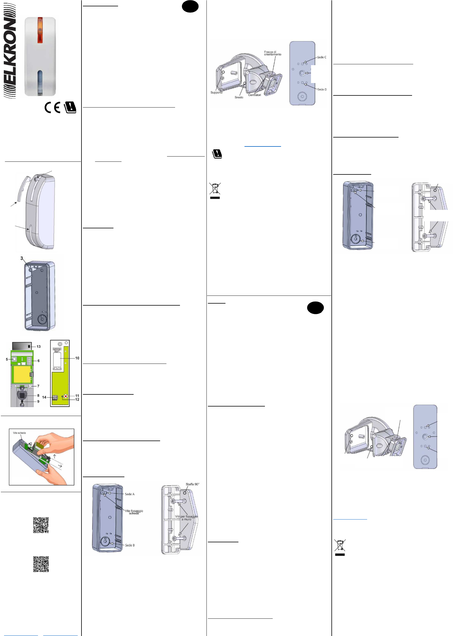
Montaggio con snodo (ref. 80SP5D00113)
Lo snodo può essere applicato in orizzontale, sia
direttamente al muro con le apposite viti e tasselli, sia tramite
il supporto.
Permette orientamenti di +/- 45° sul piano verticale e +30°,
nel verso contrario a quello delle “Frecce di Orientamento”,
sul piano orizzontale.
I. Forare le sedi C e D sul fondo
II. Orientare lo snodo e serrare la vite di bloccaggio snodo.
III. Posizionare il fondo sullo snodo con le viti di fissaggio
staffa.
DICHIARAZIONE DI CONFORMITÀ UE SEMPLIFICATA
Il fabbricante, URMET S.p.A., dichiara che il tipo di
apparecchiatura radio: RIVELATORE RADIO DOPPIA
TECNOLOGIA AD EFFETTO TENDA DT600 è conforme
alla direttiva 2014/53/UE. Il testo completo della
dichiarazione di conformità UE è disponibile al seguente
indirizzo Internet:
www.elkron.com.
FR / UK / RUS
DIRETTIVA 2012/19/UE DEL PARLAMENTO EUROPEO E
DEL CONSIGLIO del 4 luglio 2012 sui rifiuti di
apparecchiature elettriche ed elettroniche (RAEE).
Il simbolo del cassonetto barrato riportato
sull’apparecchiatura o sulla sua confezione indica
che il prodotto alla fine della propria vita utile deve
essere raccolto separatamente dagli altri rifiuti.
L’utente dovrà, pertanto, conferire l’apparecchiatura giunta a
fine vita agli idonei centri comunali di raccolta differenziata
dei rifiuti elettrotecnici ed elettronici. In alternativa alla
gestione autonoma è possibile consegnare l’apparecchiatura
che si desidera smaltire al rivenditore, al momento
dell’acquisto di una nuova apparecchiatura di tipo
equivalente.
Presso i rivenditori di prodotti elettronici con superficie di
vendita di almeno 400 m2 è inoltre possibile consegnare
gratuitamente, senza obbligo di acquisto, i prodotti elettronici
da smaltire con dimensione massima inferiore a 25 cm.
L’adeguata raccolta differenziata per l’avvio successivo
dell’apparecchiatura dismessa al riciclaggio, al trattamento e
allo smaltimento ambientalmente compatibile contribuisce
ad evitare possibili effetti negativi sull’ambiente e sulla salute
e favorisce il reimpiego e/o riciclo dei materiali di cui è
composta l’apparecchiatura.
PARTS
1. LED filter screw covers
2. Closure screws
3. Card-fastening screws
4. Lens
5. Anti-opening tamper
6. Dip Switch (never use 4 and 5: always OFF)
7. Detector capacity trimmer
8. PIR sensitive element
9. Detector LED
10. Battery compartment
11. Learning Button
12. Internal LED for the learning operations and battery
signals
13. Jumper tamper (removal protection). Intended to
connect the removal protection (optional, not
included)
14. For future uses (do not modify the position)
DETECTOR LEARNING
To open the sensor, lift the LED filter screw covers and
loosen the closure screws beneath it. Loosen the screws that
hold the electronic card in place without unscrewing them
completely and disassemble the electronic card, lifting it
upward first to release it from the screw, as illustrated
(FIG.1).
Insert the CR2 battery into the battery compartment,
taking care to observe the polarity.
When the detector LED indicator is powered, it blinks
for 60 seconds (initialisation phase). The detector is
not yet activated.
Enable the control unit for the learning device. For
details, see the control unit instruction manual.
Press the learning button on the radio circuit and
complete the learning process (see the control unit
instruction manual).
Put the control unit in “Radio Device Test” mode after
the detector learning procedure.
Insert the circuit on the bottom, tighten the screws and
close the front panel, positioning the detector in the
where it is to be installed.
Once the radio cover is checked, it is possible to
reopen the front panel, disassemble the circuit and
install the detector.
DIP SWITCH
Sensitivity Function (Increase of Sensitivity)
NORMAL: Dip Switch N°1 in OFF position (Default).
Recommended for most outdoor installations.
HIGH: Dip Switch N°1 in ON position. Recommended when
a higher detection speed is required.
Cut-off time
The detector automatically inhibits consecutive alarm
signals for a set cut-off time.
- Dip Switch N° 2 in OFF position 4 min (Default)
- Dip Switch N° 2 in ON position 8 min
Detector LED indicator
Dip Switch N° 3 in OFF position
In the normal operating mode, the LED indicator blinks to
indicate the transmission of the signal in the following
situations:
When it is powered, it blinks for 60 seconds
(initialisation phase).
When the cover is open and the tamper
switch is activated, for 4 minutes (test mode).
During the test mode for every movement
detected
If the tamper is open, for every movement
detected.
It does not blink if a movement is detected in normal
mode and with the tamper closed.
Dip Switch N°3 in ON position (Default)
The LED also blinks when a movement is detected in
normal operating mode and with the tamper closed, at
the cost of depleting the battery. It is inhibited as soon
as the cut-off time starts.
TRIMMER (SENSOR CAPACITY)
This regulates the sensor capacity (turning the trimmer
clockwise increases the detector capacity, max 8 m). To
adjust it, keep in mind the operating area determined by
the microwave. The sensor will automatically adapt the
functioning of the infra-red with this regulation. The trimmer
default position is completely clockwise turned.
TEST MODE (WALK TEST)
By opening the front panel of the sensor, after having
waited for the initialisation phase to finish, the Test Mode
is launched and lasts about 4 minutes. In this condition the
cut-off time is disabled, while the LED of the detector of the
alarm signal is automatically enabled.
INSTALLATION
Installation on flat surfaces
I. Cut seat A and seat B on the bottom (see the
image below).
II. Using the holes template, make holes on the
surface.
III. Fix the bottom using the special screws in seats A
and B.
Installation with the 90° support (ref.
80SP4D00113)
First fix the 90° support to the wall with the special screws
and then fix the base to the support using seats A and B
with the fastening screws. Re-screw the card to the base.
Installation with bracket (ref. 80SP5D00113)
The bracket can be applied horizontally, or directly to the
wall with the special screws and anchor bolts, or using the
support.
It is possible to orient the base at +/- 45° on a vertical plane
and +30°, on the side opposite the “Orientation Arrow”, on
the horizontal plane.
I. Puncture seats C and D on the base.
II. Orient the bracket and tighten the bracket
blocking screws.
III. Position the base on the bracket with the
bracket fastening screws.
SIMPLIFIED EU DECLARATION OF CONFORMITY
Hereby, URMET S.p.A. declares that the radio equipment
type: OUTDOOR DUAL TECHNOLOGY DETECTOR
WITH CURTAIN EFFECT DT600
is in compliance with
Directive 2014/53/EU. The full text of the EU declaration of
conformity is available at the following internet address:
www.elkron.com.
DIRECTIVE 2012/19/EU OF THE EUROPEAN
PARLIAMENT AND OF THE COUNCIL of 4 July 2012 on
waste electrical and electronic equipment
(WEEE).
The symbol of the crossed-out wheeled bin on
the product or on its packaging indicates that this product
must not be disposed of with your other household waste.
Instead, it is your responsibility to dispose of your waste
equipment by handing it over to a designated collection
point for the recycling of waste electrical and electronic
equipment. The separate collection and recycling of your
waste equipment at the time of disposal will help to
conserve natural resources and ensure that it is recycled
in a manner that protects human health and the
environment.
For more information about where you can drop off your
waste equipment for recycling, please contact your local
city office, your household waste disposal service or the
shop where you purchased the product.
RIVELATORE RADIO DOPPIA
TECNOLOGIA DA ESTERNO
EFFETTO TENDA
OUTDOOR DUAL
TECHNOLOGY RADIO
DETECTOR WITH CURTAIN
EFFECT
I
1
2
4
GB
Seat A
Card fastening
screw
Seat B
Wall
fastening
screw
s
Puncture to
access the
bracket
adjustment
screws
Seat D
Support
Bracket
Centering
elements
Orientation
arrows
Seat C
Accesso
vite
regolazione
snodo
FIG.1
1


Need help? Post your question in this forum.

Forumrules


Report abuse

Libble takes abuse of its services very seriously. We're committed to dealing with such abuse according to the laws in your country of residence. When you submit a report, we'll investigate it and take the appropriate action. We'll get back to you only if we require additional details or have more information to share.

Product:

For example, Anti-Semitic content, racist content, or material that could result in a violent physical act.

For example, a credit card number, a personal identification number, or an unlisted home address. Note that email addresses and full names are not considered private information.

Forumrules

To achieve meaningful questions, we apply the following rules:

Register

Register getting emails for Elkron DT600 at:


You will receive an email to register for one or both of the options.


Get your user manual by e-mail

Enter your email address to receive the manual of Elkron DT600 in the language / languages: English, German, French, Italian as an attachment in your email.

The manual is 0,42 mb in size.


You will receive the manual in your email within minutes. If you have not received an email, then probably have entered the wrong email address or your mailbox is too full. In addition, it may be that your ISP may have a maximum size for emails to receive.

Others manual(s) of Elkron DT600

Elkron DT600 User Manual - English, German, French, Italian - 24 pages


The manual is sent by email. Check your email

If you have not received an email with the manual within fifteen minutes, it may be that you have a entered a wrong email address or that your ISP has set a maximum size to receive email that is smaller than the size of the manual.

The email address you have provided is not correct.

Please check the email address and correct it.

Your question is posted on this page

Would you like to receive an email when new answers and questions are posted? Please enter your email address.


Info