4
Fig. 4
Abb. 4
30 mm
15 mm
Ø 6 mm
Ø 1,4 mm
5. Montage
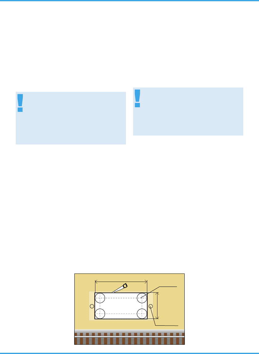
1. Sägen Sie an der Montagestelle ein Loch mit
den Maßen 30 mm x 15 mm. Bohren Sie dazu
zuerst 4 Löcher mit 6 mm Durchmesser. Ver-
wenden Sie die in der Abbildung 4 abgedruckte
Schablone.
2. Führen Sie die Anschlusskabel von oben durch
das Montageloch und stecken Sie dann das Si-
gnal mit dem Antrieb voran hinein.
3. Befestigen Sie das Signal mit den beiliegenden
Schrauben.
6. Anschluss
Alle Anschluss- und Montagearbeiten dürfen
nur bei abgeschalteter Betriebsspannung
durchgeführt werden!
Verwenden Sie nur nach VDE /EN-gefertigte
Modellbahntransformatoren!
Sichern Sie die Stromquellen unbedingt so
ab, dass es bei einem Kurzschluss nicht
zum Kabelbrand kommen kann.
Die Betriebsspannung beträgt 16 V = / ~.
Schließen Sie nun das Signal gemäß den Abbil-
dungen 6 oder 7 an. Zur Bedeutung der Kabelfar-
ben siehe Abbildung 5.
Für die Versorgung der Signalbeleuchtung emp-
fehlen wir einen separaten Transformator. Das
verhindert ein eventuelles Flackern der Beleuch-
tung beim Umschalten des Signales durch den er-
höhten Strombedarf des Antriebes.
Gleichstrombetrieb: Schließen Sie die beiden
gelben Kabel an den Minuspol des Trafos an.
Analoge Ansteuerung
In Abbildung 6 zeigen wir Ihnen, wie einfach
Sie die dreibegriffigen Formsignale mit Hilfe der
Viessmann Tastenstellpulte 5546 (ohne Rückmel-
5. Mounting
1) Saw a square hole of 30 mm x 15 mm at the
mounting place. But before 4 holes of 6 mm di-
ameter each should be drilled in the corners.
Use the pattern which is shown in figure 4.
2) The signal‘s connection wires have to be insert-
ed into the hole first. After that put the signal
with the drive first into that hole.
3) Attach the signal to the baseboard with the en-
closed screws.
6. Connections
Make sure that the power supply is switched
off when you mount the device and connect
the wires!
Only use VDE/EN tested special model train
transformers for the power supply!
The power sources must be protected to pre-
vent the risk of burning wires.
The operating voltage is 16 V (AC/DC).
Now make the electrical connection as per figure
6 or 7. For the meaning of the cable colours refer
to figure 5
As a supply for the signal light, we recommend a
separate transformer. This will prevent flickering of
the lights due to high consumption of the drive.
Connect the signal light to the transformer via the
yellow cable with black marking and the brown ca-
ble with the diode.
Direct current: Connect both yellow cables to the
negative pole of the transfomer.
Analogue Wiring
The conventional wiring is shown in figure 6. It
shows how you can connect the three-aspect form
signals to a push-button panel (e. g. 5546 without