Vehicle fe
Ampera
Quick Reference Guide
Refer to Owner’s M
Illustrations
Oper
Depending o
and access
vehicle may diff
TS 1718-B-12 / KTA 2727 September 2011
*KTA-2727*
Vehicle features Vehicle features
Unlocking the
Press button ( once to unlock
driver’s
and load compartment, press
button ( twice.
The vehicle may also be configured
to unlock al
button ( .
Open doo
Open & Start:
With remote control within range,
press lock/u
handle to unlock t
Press again w
unlock all
Providing the
was used to unlock, it can also be
used to lock the vehicle.
Locking the vehicle:
Press button ) on remote control.
Make sure door
central lockin
properly.
Press ) twice with
deadlock all doors
anti-theft alarm syste
Unlocking the vehi
the deadlocks and the
alarm system.
Electronic imm
The system checks
ignition is allo
on by verifyin
coding of the remote control in the
vehicle.
Activated automatically after
ignition is swi
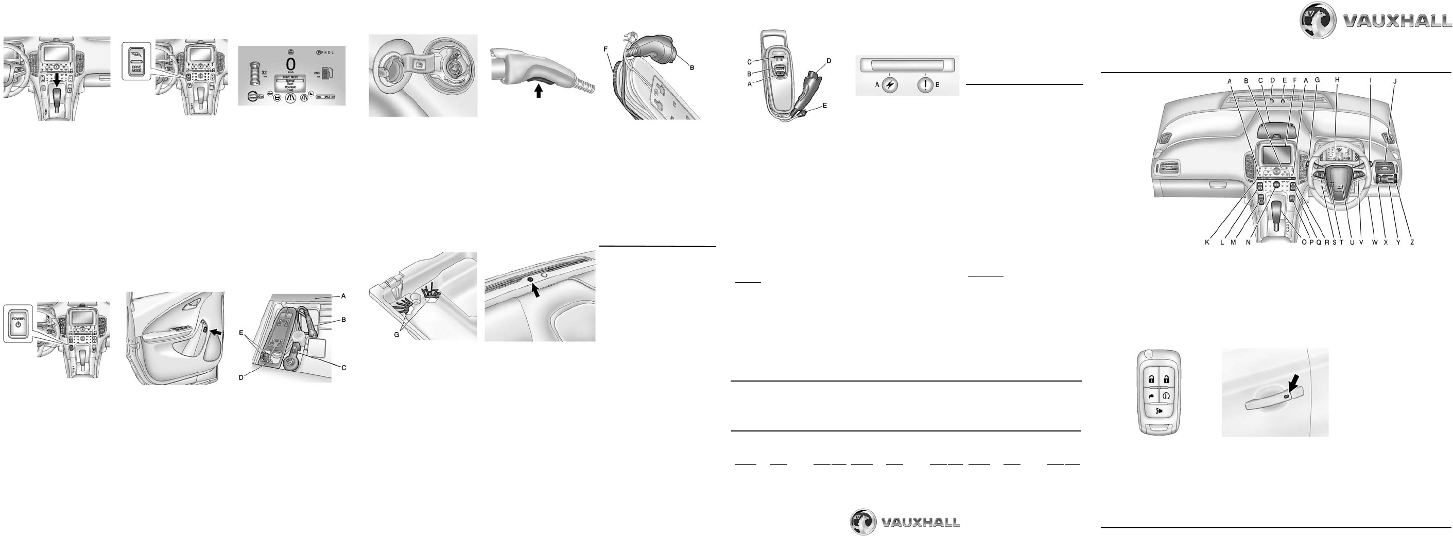
A. Heated front seats
B. Automatic climate control
C. In
D. Charge status indicator
E. Daytime runn
F. Colour-In
G. Turn and lane-change s
Light switch,
Pedestr
H. Ins
Driver Infor
I. Wipers and
J. Air vents
K. Hazard warning flas
L. Central lockin
M. Electri
N. I
O. Selector lever
P. Po
Q. Drive mode bu
R. Le
S. Cruise
T. S
U. Horn
V. Steering wheel cont
W. Da
X. Headlight ran
Y. Driver Inform
Z. Instrumen
control
Electric dr
P = Park position.
Front wheels are l
engage only whe
is stationary and the
parking br
R = Reverse gear.
Engage only wh
stationar
N = Neutral
D = Drive mode
L = Low.
Vehicle speed is r
without using b
steep hills, snow o
To move out of P , switch ignition
on, depress brake pedal and pre
selector lever button.
Electric vehi
In electric m
powered by electri
stored in the ba
In extended range mode
stored electri
exhausted, elec
by the fuel-
Drive mod
The following
be selected fr
pressing thDRIVE MODE button:
Mountain (for steep h
Select mode 20 minutes before
driving on steep grad
reserve battery char
Sport (f
acceleration)
Hold (select dur
mode to reserve battery charge.
Vehicle swit to Extended
range mode)
Release bu
is highlighted to activate mode.
Press button again to re
Normal mode.
Starting
Move selector lever to P or N.
The propul
start in any other position.
Move steering wh
release steeri
Remote control must be
the vehicle.
(A display message will ap
if the remote control is not
detected).
Depress br
Press power button m to switch
on ignition; LED
When R illuminates,
the vehicle is re
Press power button
m to switch off
ignition; LED exti
lever must be in position P.
Charging
The battery can only be charged
when the vehicle is
Start ch
1. With selector lever in posiP,
release the charge
pressing the rele
driver’s door trim panel - or -
press $ on remote control.
Start ch
2. O
covering (A and remove the
charge cord (D) , located next to
tyre repair kit (C) .
3. Pul(D)
to release it f(E).
4. Lift char
rear to remove from vehicle.
Vehicle plug (B) is stored as
shown in th
5. Plug char
outlet. Check charge
indicators are both green.
6. Se
charging screen or but
charge cord.
End charge (
5. Be
ensure it is
then wrap the charge cable
anti-clockwise around the body
of the charge cord.
Start ch
7. In
charge cord into the vehicle’s
charge
8. Che
indicator on top of the
instrument
and a horn chirp occurs.
9. Lock th
control to arm the charge cord
theft alert s
End charge:
1. Unhicle with the
remote control to disarm the
charge cord theft alert system.
2. R
the charge cord from the vehicle
by squeezing the veh
lever and pull to remove.
3. Clo
pressing firmly in the centre to
ensure it latche
4. Unpl
electrical outlet.
End charge
6. Place the charge cord face down
into the storage compartment
with the front edge (F) of the
charge cord body under the
clips (G) located in the front of
the storage compartment.
The vehicle plug (B) sh
on the right-hand side of the
charge
7. Pus
down until it locks in
clip at the rear of the storage
compartment.
To temporarily override a de
charge event, unplug the charge
cord from the cha
it back in within 5 seconds. A si
horn ch
will begin im
Charging st
The vehicle h
indicator at th
instrument pa
windscreen.
When the vehi
the vehicle po
charging status indi
the following:
Green (steady) -
one horn chirp:
Vehicle plugg
charging.
Green (steady
4 horn chirps:
Insufficient time to fully charge
before departure time.
Green (long flashing
2 horn chirps:
Vehicle plugg
charging is delayed
Charging s
Green (short flashi
No horn chirp:
Vehicle plugged
charged.
Yellow (steady) -
no horn chirp
Vehicle ha
If indicator re
malfunction ha
No light signal or horn chirp
(upon plug-i
Check charge cord connection.
No light signal or horn chirp
(after green or yellow appears):
Check charge cord connection.
No light signal -
repeated horn chirps:
Charging interrupted
charge cord or press button (
on remote control to stop this
alert.
The system may be thermally
conditioning thebattery du
any of the
electrical energy to be transferred
to the vehicle.
If the vehicle
power is on, the charging status
indicator wil
If the vehicle
charging status indic
charging fault has been detected.
If a faulty connection is not the
cause, consult a workshop.
Tyre pressure:
Check tyre pressures, iys and prior to any long journey;
checked when cold.cles with tyre pressu re monitor
The tyre pressure data refers to cold tyres. It
The ECO tyre press
Tyre pressure (psi
Comfort setting for u
3 people:
Engine
Tyres Front Rear
All 215/55 R17 35 35
225/45 R18 38 38
205/60 R16 38 38
Tyre pressure (psi
With full l
Engine
Tyres Front Re
All 215/55 36 36
225/45 R18 39 45
205/60 R16 39 45
Tyre pressure
ECO setting for upt
3 people
Engine
Tyres Front Rear
All 21 39 39
225/45 R18 41 41
205/60 R16 41 41
Charge cord:
A = Charge level bu
B =
C = Charge cord status indicators
D = Vehicle plug
E = Wall plug
A portable charge cord used to
charge the vehicle battery is stored
under the loa compartment.
The charge cord used to charg
vehicle is a hi
device. During n
the AC wall plug may feel
The AC wall plug must fit tightly
into an AC outlet that is in good
condition.
Danger:
Risk of electric shock or other
hazards if using charge cord when
any part of it
open or remove th
Do not use an AC outlet that is
worn or damage
An extension
used to charge the vehicl
Charge cord statu
When both indicators are gree
the vehicle can be charged.
If any indicator flashes red, charge
cord will not
Indicators the fo
Flashing r(A):
AC voltage out of range.
Flashing r(A) & fault (B):
AC outlet does not have proper
safety ground. Charging
permitted. Repair or replace
AC outlet.
Flashing red(B):
Charge cord fault. If flashing
continues for mo
30 s
to reset. Consult a workshop if
this fault
Charge level button:
Charge level se
using the cha
charge cord button.
Normal = 4 indicators are
(recommended)
Reduc =
(use when electrica
current is l
To change charge level, first
unplug vehicle
port and sele
Vehicle plug
The vehicle plug attaches to the
charge port of the vehicle.
There is a flas
vehicle plug that is
squeezing the veh
Engine oil:
Check eng
a regular basis to preven
to engine. Ensure that the correct
specifica
Check with vehicle on a le
surface
operating temperatu
switched o min
Pull out dipstick, wipe cle
to stop on the handle
read engine
If the engine
cross-hatche
top up engine oi
Insert dipstick to stop on handle
and make half a turn.
We recommend the use of the
same gradne oil that was
used at the last change.
Important:
It is the owner’s responsibility to
maintain the correct le
appropriate quality o
engine.
Do not allo
drop below the minimum leve