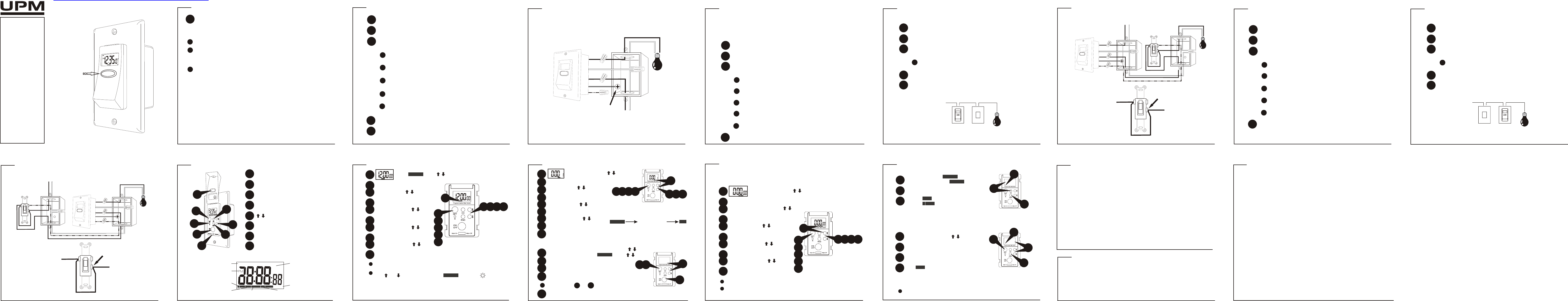
ETW353 electronic programmable timer
OWNER’S
MANUAL
Congratulations on your
purchase of a UPM timer.
Please take the time to
read and understand this
manual so you can begin
to enjoy the security and
energy saving benefits this
product has to offer.
FEATURES
! 20 ON programs /
20 OFF programs
! Countdown timer -
“One-Touch Countdown”
! 3 random functions
! 12/24 hour clock
! 15A, 1800W (resistive)
! single pole or three-way
SINGLE POLE INSTALLATION
1
2
Remove existing switch and identify the wires in the wall box.
Using the supplied wire nuts, securely fasten the wires on the timer
to the wires in the wall box according to diagram FIGURE 1.
3
Disconnect the power supply at the circuit breaker or fuse before
proceeding with the installation.
Connect the black (hot) wire on the timer to the hot wire in the
wall box.
Connect the blue (hot) wire on the timer to the hot wire in the
wall box coming from the light fixture.
GETTING STARTED
setting the clock
1
4
2
1
5
6
7
8
Press SET
Day select with
Press SET
Hour select with
Press SET
Minute select with
3
5
7 9
2
4
6
8
10
9
10
3
Press SET
Second select with
Press SET
Press SET
Minute select with
memory backup
This UPM wall switch timer comes with built-in memory backup protection. In the
event of a power outage, all program and clock settings will remain in memory.
CLOCK
ON
MO
CLOCK
ON
MO
To activate/deactivate Daylight Saving Time (DST) function, pre
both and together for 3 seconds in mode; solid for DST
CLOCK
To toggle between 12/24 hour format, press RND during clock setting
CAUTION!
*
This timer must NOT be used on loads exceeding 1800W.
All wiring must comply with applicable codes and regulations.
TO AVOID FIRE, SHOCK, OR DEATH; SHUT OFF POWER SUPPLY A
THE CIRCUIT BREAKER OR FUSE AND TEST THAT THE POWER IS
OFF BEFORE WIRING.
Handle installation with caution to prevent any risk of electrical shock
that could cause serious injury or death. If you are not sure about any
part of the given instructions, consult a qualified electrician.
For proper grounding, connect the green (ground) wire on
the timer to the ground “screw” found inside the wall box.
Mount timer into the wall box carefully.
Restore power supply at the circuit breaker or fuse.
4
5
SINGLE POLE INSTALLATION DIAGRAM
Terminate the red (three-way) wire on the timer with a wire nut.
(For a single pole installation, the red wire is not needed).
FIGURE 1
Hot Switch
Power Source
3-Way
Timer
Restore power supply at the circuit breaker or fuse.
8
THREE-
ADDING A JUMPER WIRE TO THE HOT SWITCH
*
Disconnect the power supply at the circuit breaker or fuse before
proceeding with the installation.
5
Take out the HOT switch and identify the common terminal.
6
Connect the jumper wire to the HOT switch according to diagram
FIGURE 3.
Connect the jumper wire from the common terminal to the
hot terminal of the HOT switch.
Mount HOT switch back into the wall box carefully.
7
INSTALLING THE TIMER IN PLACE OF LOAD SWITCH
FIGURE 3
THREE-
Connect the white (neutral) wire on the timer to the neutral
wires in the wall box.
Screw
Red
Green
White
ETW353
Blue
Black
LOAD
Power Source
JUMPER WIRE
COMMON TERMINAL
HOT WIRE
HOT WIRE
CLOSE UP VIEW OF THE HOT SWITCH
Power Source
Red
ETW353
JUMPER
3 Way
Blue
Black
LOAD
COMMON
Green
HOT SWITCH
White
Go to using
CLOCK
PROG
ON
MO TU WE TH FR SA SU
1
3
5
7
2 4 6 8
PROG
ON
MO TU WE TH FR SA SU
4
3
2
1
X
THREE-
1
2
Remove existing switch and identify the wires in the wall box.
Using the supplied wire nuts, securely fasten the wires on the timer
to the wires in the wall box according to diagram FIGURE 2.
3
Disconnect the power supply at the circuit breaker or fuse before
proceeding with the installation.
Connect the black (hot) wire on the timer to the hot wire in the
wall box.
Connect the blue (hot) wire on the timer to the load wire in
the wall box coming from the LOAD switch.
Connect the red (three-way) wire on the timer to the three-way
wire in the wall box coming from the LOAD switch.
Mount timer into the wall box carefully.
Restore power supply at the circuit breaker or fuse.
4
8
THREE-
There are two switches in a three-way circuit. The switch directly
connected to the circuit breaker is the HOT switch. The second switch is
the LOAD switch. Ensure you know which switch you are replacing.
INSTALLING THE TIMER IN PLACE OF HOT SWITCH
For proper grounding, connect the green (ground) wire on
the timer to the ground “screw” found inside the wall box.
ADDING A JUMPER WIRE TO THE LOAD SWITCH
*
Disconnect the power supply at the circuit breaker or fuse before
proceeding with the installation.
5
Take out the Lcommon terminal.
6
Connect the jumper wire to the LOAD switch according to diagram
FIGURE 2.
Connect the jumper wire from the common terminal to the
hot terminal of the LOAD switch.
Mount LOAD switch back into the wall box carefully.
7
Load Switch
Power Source
3-Way
Timer
Connect the white (neutral) wire on the timer to the neutral
wires in the wall box.
TROUBLESHOOTING
LCD display seems “frozen”.
Buttons won’t respond.
Programmed ON/OFF times
don’t execute.
Programmed ON/OFF times
don’t execute at specified times.
Three-way switch is not working
properly.
Press reset button to reset timer.
Ensure that the program disable
feature is not enabled.
Ensure that the random function
is not enabled.
Disconnect power supply at the
circuit breaker or fuse. Check
installation for proper wiring.
problem solution
TECHNICAL SPECIFICATIONS
Program: 20 programs
Ratings: 120V AC, 15A
Max Load: 1800W resistive, 600W tungsten; single pole or three-way
Min switching time: 1 minute
Select program 20 with
Flashing for short random
Flashing for long random
RANDOM FUNCTION
3
2
1
short/long random
programmable random
4
1
2
Press RND
Set program 20 to desired random time
3
4
1
2
Press RND
3
Short random from
OR Long random from
CLOCK
CD
RND
L
RND
-
Solid for programmable random
RND
* Short random 1-2 hours, long random 2-3 hours
* Programmable random only works with program 20; 1-2 hours
3
2
1
Deactivate random function with RND or ON/OFF
Power Source
INSTALLING THE TIMER IN PLACE OF HOT SWITCH
THREE-
THREE-
1
2
Remove existing switch and identify the wires in the wall box.
Using the supplied wire nuts, securely fasten the wires on the timer
to the wires in the wall box according to diagram FIGURE 3.
3
Disconnect the power supply at the circuit breaker or fuse before
proceeding with the installation.
Connect the blue (hot) wire on the timer to the hot wire in the
wall box coming from the lighting fixture.
Connect the black (hot) wire on the timer to the hot wire in
the wall box coming from the HOT switch.
Connect the red (three-way) wire on the timer to the three-way
wire in the wall box coming from the HOT switch.
Mount timer into the wall box carefully.
4
INSTALLING THE TIMER IN PLACE OF LOAD SWITCH
For proper grounding, connect the green (ground) wire on
the timer to the ground “screw” found inside the wall box.
Connect the white (neutral) wire on the timer to the neutral
wires in the wall box.
Red
ETW353
JUMPER
3 Way
Black
Blue
LOAD
COMMON
Green
JUMPER WIRE
COMMON TERMINAL
HOT WIRE
HOT WIRE
FIGURE 2
CLOSE UP VIEW OF THE LOAD SWITCH
LOAD SWITCH
White
GETTING STARTED
button placements
display
1
2
CD - activates countdown timer
3
4
SET - activates set functions
RND - activates random functions
5
- scrolls through selections
6
ON/OFF - manual on/off control
7
Main On/Main Off
R - reset
1
4
2
5
6
7
3
CLOCK CD
SET
RND
L
-
PROG
ON
MO TU WE TH FR SA
X
Set function indicator
Weekday indicators
Random function indicator
AM/PM
Clock function
indicator
Disabled program
icon
ON/OFF indicator
8
8
One-T
COUNTDOWN TIMER
1
4
2
5
6
7
8
Press SET
Start ON or OFF select with
Press SET
Hour select with
Press SET
Minute select with
9
10
3
Press SET
Second select with
Press SET
The to-the-second countdown feature of this timer starts from the ON or OFF
position and counts down to zero when activated.
CD PROG
ON
3
5
7 9
1
2
4
6
8
10
CD
PROG
ON
Stop countdown timer with CD (or One-T) or ON/OFF
Select CD mode using
Press CD or the One-T to start the countdown timer.
One-T
Countdown
Countdown function indicator
PROGRAM SETTINGS
disable program/master disable
1
4
2
5
7
8
*
*
Press SET
Day select with
* Individual days / weekly selections
Press SET
Hour select with
Press SET
Minute select with
3
Press SET
Each program has an “ON” and “OFF” setting. Both must be set for operation.
Example: PROG 1 has an “ON” and “OFF”
Program select with
1
2
Press SET
Press ON/OFF to disable ( X )
3
For single disable select PROGRAM with
For master disable go to using
Press SET 3 times to exit (single disable)
OR press SET 4 times to exit (master)
CLOCK
Programs are arranged in a circular pattern
with the clock and countdown functions:
CLOCK
Program 1–20
CD
4
Repeat steps to to undo disable ( X )
1
4
For a single program disable, both the “ON” and “OFF” setting must be disabled
individually
6
LIMITED FOUR-
UPM warrants this product, excluding battery, to be free from defects in the materials or workmanship, under normal use and
service, for a period of four years from the date of purchase by the consumer.
If, at any time during the warranty period, the product is defective or malfunctions, UPM shall repair or replace it (at UPM's
discretion) within a reasonable period of time.
If the product is defective,
(i) return it, with a dated proof of purchase, to the retailer from which you purchased it, or
(ii) package it carefully, along with a dated proof of purchase and a short description of the malfunction, and mail it, postage
prepaid, to the following address:
UPM Marketing Inc.
Return Goods
Unit 10B 250 Shields Court
Markham, Ontario
L3R 9W7
This warranty does not cover removal or reinstallation costs. This warranty shall not apply if it is shown by UPM that the defect or
malfunction was caused by damage which occurred while the product was in the possession of the consumer.
UPM's sole responsibility shall be to repair or replace the product within the terms stated above. UPM SHALL NOT BE LIABLE FOR
ANY LOSS OR DAMAGE OF ANY KIND, INCLUDING ANY INCIDENTAL OR CONSEQUENTIAL DAMAGES RESULTING, DIRECTL
OR INDIRECTLY
PRODUCT. Some states do not allow the exclusion or limitation of incidental or consequential damages, so this limitation may not
apply to you.
THIS WARRANTY IS THE ONLY EXPRESS WARRANTY UPM MAKES ON THIS PRODUCT
WARRANTIES, INCLUDING THE WARRANTIES OF MERCHANTABILITY AND FITNESS FOR A PARTICULAR PURPOSE, IS
HEREBY LIMITED TO THE FOUR YEAR DURATION OF THIS WARRANTY
implied warranty lasts, so the above limitation may not apply to you.
This warranty gives you specific legal rights, and you may have other rights which may vary from state to state.
If you have any questions concerning this warranty, please write to:
UPM Marketing Inc.
Customer Service Department
Unit 10B 250 Shields Court
Markham, Ontario
L3R 9W7
Or call 1-888-GO-TO-UPM (1-888-468-6876), Monday to Friday, from 9:00am to 5:00pm eastern.
(4)
http://waterheatertimer.org/UPM-timers-and-manuals.html