1. Applications
The electronic floor temperature controller is used for
controlling electric:
• direct floor heating
• floor temperature conditioning systems
Features
• Nighttime set-back, input for external clock
• Indicator lamps for "controller calls for heat" and for
set-back operation
• 2-pole mains switch
• Mounting in 60mm flush-type box
2. Description of functions
2.1 Functions
The floor temperature is set via the dial and is measured
by the remote sensor.
The scale of *…5 corresponds to a temperature of
10…50 °C.
Lamps
Red: Controller calls for heat
Green: Set-back mode is activated
2.2 Functions of the set-back input TA
The TA input is used to set various set-back functions,
refer to table below.
The functions are selected via the mains sine half-waves.
The functions correspond to the "Pilot wire" specificati-
on.
Caution-1!
The device may only be opened and installed ac-
cording to the circuit diagram on the device or these
instructions by a qualified electrician. The existing
safety regulations must be observed.
In order to comply with safety class II, the necessary
installation steps must be taken.
This independently mountable electronic device is de-
signed for controlling the temperature in dry and en-
closed rooms only under normal conditions. The devi-
ce confirms to EN 60730, it works according operating
principle 1C
468 931 003 454
Mounting and
Operating Instructions
Electronic floor temperature controller
with set-back input
RAM 751
Half-wave Function
none no set-back
both set-back acc. to J2
positive control off
negative anti-freeze = 10°C
both pulsed short set-back by 1°C
both pulsed long set-back by 2°C
The anti-freeze function regulates to a temperature of
10°C.
This multi-function input makes it possible to activate
controller functions by means of the various half-waves
of the mains AC voltage:
Normal operation: input open – – – –
Temp. set-back: both half-waves
Ä
Anti-freeze: negative half-wave Å
Heating off: positive half-wave Ç
2.3 Selecting the set-back temperature
By means of the J2 jumper it is possible to select 3°
or 5°.
J2 closed set-back by 5°C (factory pre-set)
J2 open set-back by 3°C
The temperature set externally via the dial is reduced by
this value.
2.4 Fault of the floor sensor
If a sensor fault (short-circuit or break) occurs, the con-
troller will switch to fault mode. The heating will func-
tion with max. 30 % of the energy (operation for 30 % of
the time). This provides frost- and overheat protection.
In the event of a sensor fault, both lamps will flash.
2.5 Function of the lamps
Function Lamp green Lamp red
Heating is on on
Set-back mode on
Floor sensor fault flashes flashes
3. Electrical connection
Perform the steps described below:
• Pull off the temperature dial
• Release the fixing screw
• Remove the upper part of the casing
• Connect acc. to circuit diagram (see bottom of casing)
Floor sensor F 193 720
The remote sensor must be mounted in such a way that
the temperature to be limited can be correctly re-
corded.
The remote sensor should be installed in a protective
tube. This will facilitate future replacement.
Do not install the sensor close to power lines. In other
cases a shilded cable has to be used.
The sensor can be extended to max. 50 m by means of
a cable suitable for mains voltage.
Caution!
The sensor lines are on mains voltage (230 V).
Caution! De-energize the electric circuit first
4. Technical data
Order designation RAM 751
EDP No.: 751 0 131
Temperature setting range:
Floor temperature *…5 (= 10…50ºC)
Indicator lamp red Controller calls for heat
green Set-back temperature
Power switch 2-pole
Supply voltage 230 V AC (195…253 V) 50 Hz
Output Relay make contact
Switching current 100 mA…16 A cosϕ = 1;
100mA… 4A cosϕ = 0.6
Control algorithm Proportional controller
(similar to continuous
through PWM)
Switching temperature
differential ~1°C
Temperature sensor Type F 193 720 (length 4 m,
can be extended to max. 50 m)
Temperature set-back 3 K or 5 K selectable s. 2.3
vie external timer
Range limitation in the dial
Degree of protection
of casing IP 30
Safety class II (see Caution-1)
Degree of pollution 2
Software class A
Calculation impulse voltage 2,5 kV
Temperature for the
Ball compression test 75°C
Voltage and Current for
the for purposes of inter-
fernce measurements 230V, 0.1 A
Ambient temperature 0…40ºC
Storage temperature –25…70ºC
Weight 90 g
Characteristics for remote sensor
10°C 66.8 kΩ 30°C 26.3 kΩ
20°C 41.3 kΩ 40°C 17.0 kΩ
25°C 33 kΩ 50°C 11.3 kΩ
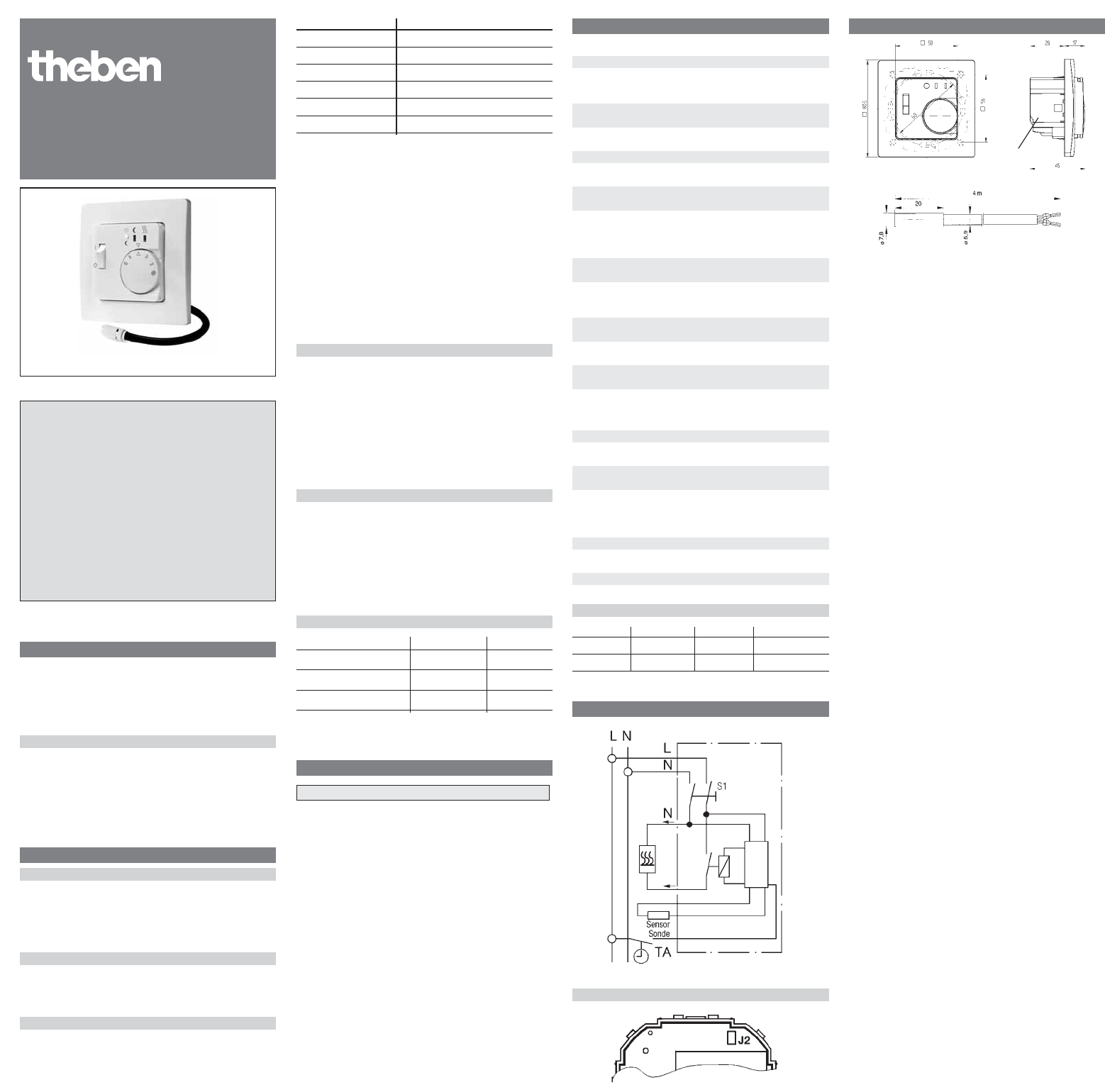
5. Circuit diagram
Position of the jumpers
6. Dimensions
Theben AG · Hohenbergstr. 32
72401 Haigerloch · DEUTSCHLAND
Fon +49 (0) 74 74/ 6 92- 0
Fax +49 (0) 74 74/ 6 92- 150
Service
Fon +49 (0) 74 74 /6 92 -369
Fax +49 (0) 74 74/ 6 92- 207
hotline@theben.de
Adresses, telephone numbers etc.
at www.theben.de
cover 2 parts (50x50)
for conduit boxes
according to DIN 49073