182 mm
53 mm
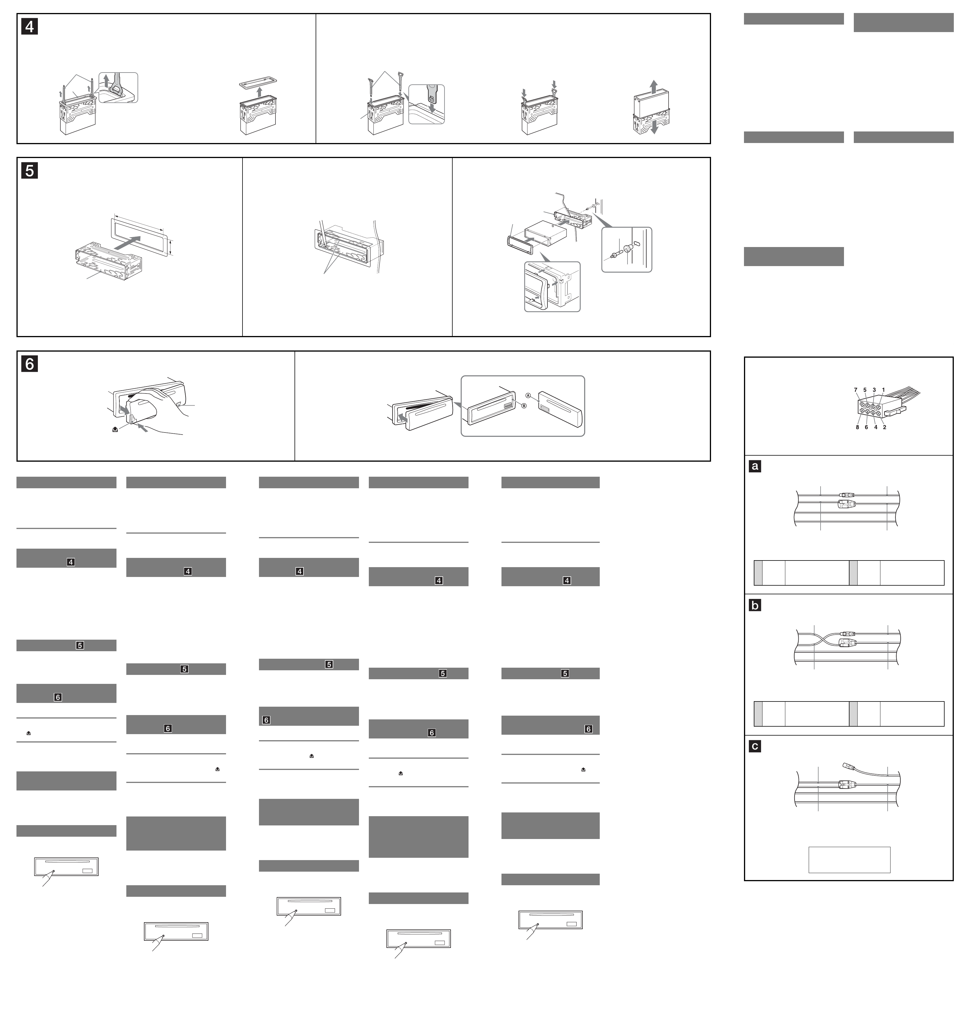
Power connection diagram
Auxiliary power connector may v
car
to make sure the connections match correctly
three basic types (illustrated below).
switch the positions of the red and yellow leads in the car
stereo’
After matching the connections and switched power
supply leads correctly
power supply
connecting your unit that are not covered in this manual,
please consult the car dealer
Auxiliary power connector
Hilfsstromanschluss
Connecteur d’alimentation auxiliaire
Connettore di alimentazione
accessoria
Hulpvoedingsaansluiting
Red
Rot
Rouge
Rosso
Rood
Red
Rot
Rouge
Rosso
Rood
Ye
Gelb
Jaune
Giallo
Geel
Ye
Gelb
Jaune
Giallo
Geel
Red
Rot
Rouge
Rosso
Rood
Red
Rot
Rouge
Rosso
Rood
Ye
Gelb
Jaune
Giallo
Geel
Ye
Gelb
Jaune
Giallo
Geel
Red
Rot
Rouge
Rosso
Rood
Red
Rot
Rouge
Rosso
Rood
Ye
Gelb
Jaune
Giallo
Geel
Ye
Gelb
Jaune
Giallo
Geel
Voedingsaansluitschema
De hulpvoedingsaansluiting kan v
van de auto. Controleer het v
dat bij dit apparaat wordt gele
aansluitingen kloppen. Er zijn drie basistypes (zie
afbeelding hieronder). Het is mogelijk dat u de posities
van de rode en gele kabels in het aansluitsnoer v
car audiosysteem moet omwisselen.
Als de aansluitingen en geschakelde voedingskabels
kloppen, sluit u het apparaat aan op de voeding v
auto. Indien u nog vragen of problemen hebt in verband
met het aansluiten van het apparaat die niet in deze
handleiding vermeld staan, raadpleeg dan de autodealer
Diagramma dei collegamenti di
alimentazione
Il connettore di alimentazione accessoria può variare a
seconda della macchina. Controllare il diagramma del
connettore di alimentazione accessoria della macchina
per essere sicuri che i collegamenti corrispondano
correttamente.
sotto). Potrà essere necessario cambiare le posizioni dei
fi
della macchina.
Dopo av
av
l’apparecchio all’alimentazione della macchina. Se si
hanno domande o se sorgono problemi che non sono
stati trattati nel manuale nel collegare l’apparecchio,
contattare l’autoconcessionario.
Schéma de raccordement
d’alimentation
Le connecteur d’alimentation auxiliaire peut varier
suiv
connecteur d’alimentation auxiliaire de votre v
pour vous assurer que les conne
en existe trois types de base (illustrés ci-dessous). Il se
peut que vous de
jaune du cordon d’alimentation de l’autoradio.
Après av
correctement les fi
à l’alimentation de la voiture. Si v
ou des diffi
abordées dans le présent mode d’emploi, consultez votre
concessionnaire automobile.
Stromanschlussdiagramm
Der Hilfsstromanschluss kann je nach Fahrzeugtyp
unterschiedlich sein. Sehen Sie im Hilfsstroman-
schlussdiagramm für Ihr Fahrzeug nach, wie die
V
Es gibt, wie unten abgebildet, drei grundlegende T
Sie müssen möglicherweise die rote und gelbe Leitung
des Stromversor
vertauschen.
Stellen Sie die
geschalteten Stromversorgungsleitungen richtig an und
verbinden Sie dann das Gerät mit der Stromversor
Ihres Fahrzeugs.
Geräts Fragen oder Probleme auftreten, die in dieser
Bedienungsanleitung nicht erläutert werden, wenden Sie
sich bitte an den
Précautions
• Choisir soigneusement l’emplacement de l’installation
afi
véhicule.
• Eviter d’installer l’appareil dans un endroit exposé à de
la poussière, de la saleté, des vibrations violentes ou à
des températures élev
proximité d’un conduit de chauff
• Pour garantir un montage sûr
fourni.
Réglage de l’angle de montage
Ajuster l’inclinaison à un angle inférieur à 45°.
Retrait du tour de protection et
du support
A
protection et le support de l’appareil.
1 Enclenchez le tour de pr .
simultanément dans le tour de protection .
pour retirer le
tour de protection .
2 Retirez le support .
simultanément entre l’appareil et le support
jusqu’au déclic indiquant qu’elles sont en
place.
v
l’appareil vers le haut pour les séparer
Exemple de montage
Installation dans le tableau de bord
Remarques
• Pliez ces gr
( -
2
).
• Assurez-vous que les 4 loquets du tour de protection sont
correctement insérés dans les fentes de l’appareil ( -
3
).
Retrait et fi
A
-A P
A
. Appuyez
, puis faites glisser la
façade vers v
-B P xe
Fixez la partie de la façade sur la partie de
l’appareil, comme indiqué sur l’illustration, puis appuyez
sur le côté gauche jusqu’au déclic.
Avertissement au cas où le
contact de votre voiture ne
dispose pas d’une position ACC
Après av
maintenir de l’appareil enfoncée jusqu’à
ce que l’affi c
Sinon, l’affi
décharge.
T
Une fois que l’installation et les raccordements sont
terminés, retirez la façade et appuyez sur le bouton
RESET à l’aide d’un stylo à bille ou d’un autre objet
pointu.
Precautions
• Choose the installation location carefully so that the
unit will not interfere with normal driving operations.
• A
excessi
direct sunlight or near heater ducts.
• Use only the supplied mounting hardware for a safe
and secure installation.
Mounting angle adjustment
Adjust the mounting angle to less than 45°.
Removing the protection collar
and the bracket
Before installing the unit,
collar and the bracket fr
1 Remove the pr .
together with the
protection collar .
to remo
protection collar .
2 Remove the brac .
together between
the unit and the bracket until they click.
, then pull up the unit
to separate.
Mounting example
Installation in the dashboard
Notes
• Bend these claws outward for a tight fi( -
2
).
• Make sure that the 4 catches on the protection collar are
properly engaged in the slots of the unit ( -
3
).
How to detach and attach the
front panel
Before installing the unit,
-A T
Before detaching the front panel, be sure to press .
Press
, and pull it off to
-B T
Engage part of the front panel with part of the unit,
as illustrated, and push the left side into position until it
clicks.
Warning if your car’
has no ACC position
After turning off the ignition,
and hold on the unit until the display
disappears.
Otherwise, the display does not turn off and this causes
battery drain.
RESET button
When the installation and connections are completed, be
sure to press the RESET button with a ballpoint pen, etc.,
after detaching the front panel.
Sicherheitshinweise
• W
Gerät beim Fahren nicht hinderlich ist.
• Bauen Sie das Gerät so ein, dass es keinen hohen
T
W
Schmutz und keinen starken
• Für eine sichere Befestigung verwenden Sie stets die
mitgelieferten Montageteile.
Hinweis zum Montagewinkel
Das Gerät sollte in einem W
montiert werden.
Abnehmen der Schutzumrandung
und der Halterung
Nehmen Sie vor dem Installieren des Geräts die
Schutzumrandung und die Halterung v
Gerät ab.
1 Entfernen Sie die Schutzumrandung .
an der
Schutzumrandung an.
mithilfe
der Löseschlüssel heraus.
2 Entfernen Sie die Halterung .
zwischen
dem Gerät und der Halterung ein, bis sie
mit einem Klicken einrasten.
nach unten
und das Gerät nach oben, um die beiden zu
trennen.
Montagebeispiel
Installation im Armaturenbrett
Hinweise
• Falls erforderlich, biegen Sie diese Klammern für einen
sicheren Halt nach außen ( -
2
).
• Achten Sie darauf, die 4
Schutzumrandung korrekt in die A
einzusetzen ( -
3
).
Abnehmen und Anbringen der
Frontplatte
Nehmen Sie die Frontplatte v
Geräts ab.
-A Abnehmen
Schalten Sie das Gerät vor dem
Frontplatte unbedingt mit aus. Drücken Sie
und ziehen Sie sie auf sich zu heraus.
-B Anbringen
Setzen Sie T der Frontplatte wie in der
dargestellt an des Geräts an und drücken Sie die
linke Seite der Frontplatte an, bis sie mit einem Klicken
einrastet.
Warnhinweis, wenn die Zündung
Ihres Fahrzeugs nicht über eine
Zubehörposition (ACC oder I)
verfügt
Nachdem Sie die Zündung ausgeschaltet haben,
halten Sie am Gerät unbedingt gedrückt,
bis die Anzeige ausgeblendet wird.
Andernfalls wird die
Autobatterie wird Strom entzogen.
T
W
vor
abnehmen und mit einem Kugelschreiber oder einem
anderen spitzen Gegenstand die T
Precauzioni
• Scegliere con attenzione la posizione per l’installazione
in modo che l’apparecchio non interferisca con le
operazioni di guida del conducente.
• Evitare di installare l’apparecchio dove sia soggetto ad
alte temperature, come alla luce solare diretta o al getto
di aria calda dell’impianto di riscaldamento, o dove
possa essere soggetto a polvere, sporco e vibrazioni
eccessiv
• Usare solo il materiale di montaggio in dotazione per
un’installazione stabile e sicura.
Regolazione dell’angolo di montaggio
Regolare l’angolo di montaggio in modo che sia inferiore
a 45°.
Rimozione della staffa e della
cornice di protezione
Prima di installare l’apparecchio,
la cornice di protezione e la staffa
dall’apparecchio.
1 Rimuo .
nella cornice
di protezione .
estrarre le chiav .
2 Rimuo .
chiav tra l’apparecchio e la
staff
fi
, quindi solle
l’apparecchio per rimuoverlo.
Esempio di montaggio
Installazione nel cruscotto
Note
• Piegare verso l’esterno questi morsetti per un’installazione più
sicura, se necessario ( -
2
).
• Assicurarsi che i 4 fermi sulla cor siano
correttamente inseriti negli alloggiamenti dell’apparecchio
( -
3
).
Come rimuovere e reinserire il
pannello anteriore
Prima di installare l’apparecchio rimuo
pannello anteriore.
-A P
Prima di rimuovere il pannello anteriore, premere
. Premere
, quindi tirare verso di sé il pannello
anteriore.
-B P
Applicare la parte del pannello anteriore alla parte
dell’apparecchio come mostrato nell’illustrazione e
premere il lato sinistro fi
Avvertenza relativa
all’installazione su un’auto
sprovvista della posizione ACC
(accessoria) sul blocchetto di
accensione
Dopo avere spento il motore,
tenere premuto sull’apparecchio fi nc
display non scompare.
Div
potrebbe causare lo scaricamento della batteria.
T
Una volta completate le procedure di installazione e i
collegamenti, accertarsi di premere il tasto RESET con
una penna a sfera o un oggetto simile dopo av
il pannello anteriore.
1
2
12 3
A
B
Dashboard
Armaturenbrett
T
Cruscotto
Dashboard
Fire wall
Motorraumtrennwand
Par
Parete ta amma
Brandschot
Face the hook inwar
Der Haken muss nach innen
weisen.
T
l’intérieur
Con il gancetto rivolto ver
l’interno.
Het haakje moet naar binnen
wijzen.
Claws
Klammern
Griffes
Morsetti
Klemhaken
Orient the release key correctly
Richten Sie den Löseschlüssel
korrekt aus.
Orientez correctement la clé de
déblocage.
Orientare la chiavetta di rilascio nel
modo corretto.
Plaats de ontgrendelingssleutel op
de juiste manier
(OFF)
Voorzorgsmaatregelen
• Kies de installatieplaats zorgvuldig zodat het apparaat
de bestuurder niet hindert tijdens het rijden.
• Installeer het apparaat niet op plaatsen waar het
blootgesteld wordt aan hoge temperaturen, b
direct zonlicht of bij de warme luchtstroom v
autoverw
contact komt met veel stof of vuil.
• Gebruik voor het v
het apparaat uitsluitend de bijgelev
onderdelen.
Maximale montagehoek
Installeer het apparaat nooit onder een hoek van meer
dan 45° met het horizontale vlak.
De beschermende rand en de
beugel verwijderen
V
u de beschermende rand en de beugel
verwijderen van het apparaat.
1 V .
op de
beschermende rand .
naar u toe
om de beschermende rand te verwijderen.
2 V .
tussen het
toestel en de beugel tot deze vastklikk
omlaag en trek het
apparaat omhoog om deze van elkaar te
scheiden.
Montagevoorbeeld
Montage in het dashboard
Opmerking
• Indien nodig kunt u deze klemhaken ombuigen voor een
steviger be( -
2
).
• De 4 grepen op de bescher moeten goed in de
sleuven v( -
3
).
Verwijderen en bevestigen van
het afneembare voorpaneel
V
beginnen,
-A V
V
op te drukken. Druk verv
toets
en trek het naar u toe.
-B Bevestigen
Breng deel van het v van
het apparaat zoals afgebeeld en druk op de linkerzijde
tot deze vastklikt.
Waarschuwing als het
contactslot van de auto geen
ACC-positie heeft
Als de motor is uitgeschakeld,
drukken en deze toets ingedrukt houden tot de
weergave ver
Als u dit niet doet, wordt de weerga
en raakt de accu uitgeput.
RESET
Als u de installatie en aansluitingen hebt voltooid,
moet u met een puntig voorwerp, zoals de punt v
balpen, op RESET drukken nadat u het voorpaneel hebt
verwijderd.
the car without A
Fahrzeug ohne Zubehörposition (A
Véhicule sans position A
Auto priv
Auto zonder A
4
Ye
Gelb
Jaune
Giallo
Geel
continuous power suppl
permanente Stromversor
alimentation continue
alimentazione continua
continu v
7
Red
Rot
Rouge
Rosso
Rood
switched po
geschaltete Stromversor
alimentation commutée
alimentazione commutata
geschakelde voeding
4
Ye
Gelb
Jaune
Giallo
Geel
switched po
geschaltete Stromversor
alimentation commutée
alimentazione commutata
geschakelde voeding
7
Red
Rot
Rouge
Rosso
Rood
continuous power suppl
permanente Stromversor
alimentation continue
alimentazione continua
continu v