Montage Farbset und
Schalterrahmen
a) Bauschutzkappe entfernen.
b) Evtl. Schalterwippe aufstecken.
c) Gehäusedeckel mit Schalterrahmen aufset-
zen, Gehäusedeckel links oben in Gehäuse-
unterteil (Regler) einrasten und Schraube
eindrehen. Einstellknopf aufstecken.
Kurzbezeichnungen Im Schaltbild:
L = Phase
N = Nulleiter
N
= Anschluß für Zeitschaltuhrsignal zur
Temperaturabsenkung
U
= Lastanschluß Heizen
P
= Lastanschluß Kühlen
RF = Widerstand für thermische Rückführung
TA = Widerstand für Temperaturabsenkung
Technische Daten
Typ 5TC9 200 5TC9 201 5TC9 202
Schaltkontakt Öffner Wechsler Öffner
Einstellbereich 5…30°C 5…30°C 5…30°C
Nennspannung AC 250V AC 250 V AC 250V
Nennstrom
U Heizen 10(4)A 10(4)A 10(4)A
P Kühlen –– 5(2)A ––
Schaltleistung
U Heizen 2,2kW 2,2kW 2,2kW
P Kühlen –– 1,1kW ––
Schalttemperatur- ca. 0,5K ca. 0,5K ca. 0,5K
differenz mit ther-
mischer Rückführung
Temp.-absenkung ca. 4K – ca. 4K
Room temperature
controller
Status April 2002
Operating and
installation instructions
The controller–base types
5TC9 200
5TC9 201
5TC9 202
are adaptable to the following
switching programs:
DELTA plus
DELTA profil
DELTA style
DELTA ambinte
DELTA i-system
(DELTA vita, DELTA line)
General Notes:
●
VDE regulations require that the installation
and operating guide be available at all times
and that it be given to the service man for in-
formation when work is being carried out
the equipment. In the event of moving hou-
se, you are requested therefore to transfer
the guide to the new owner or occupier.
●
The controller may be installed or commis-
sioned by qualified personnel only. Current
safety regulations must be observed.
●
The room temperature controller is fitted
with radio interference suppression in com-
pliance with VDE 0875 and EN 55014, respec-
tively and works according to operating
principle 1C (EN 60730).
●
The maximum permitted relative humidity is
95%. Operation in a dew-laden atmosphere
is not permitted.
●
When commissioning the room temperatu-
re regulator, please note that the bimetallic
element requires a certain time to adjust its-
elf to the room temperature. Immediately af-
ter installation the switch-point will deviate
from the room temperature. Switch-point
accuracy is established only after about 1-2
hours operation.
Field of application:
The room temperature controller is intended
for the control of temperature within enclosed
dry areas with typical surrounding.
Operation:
Scales for temperature setting with co-
demarks:
PP
corresponds to 5°C approx.
2 corresponds to 10°C approx.
3 corresponds to 15°C approx.
● corresponds to 20°C approx.
5 corresponds to 25°C approx.
6 corresponds to 30°C approx.
Symbols
(for controllers with 3-position switch only:)
N Automatic (night-time reduction remotely
controllable via time switch)
L Continuous day-time setting
M Continuous night-time setting
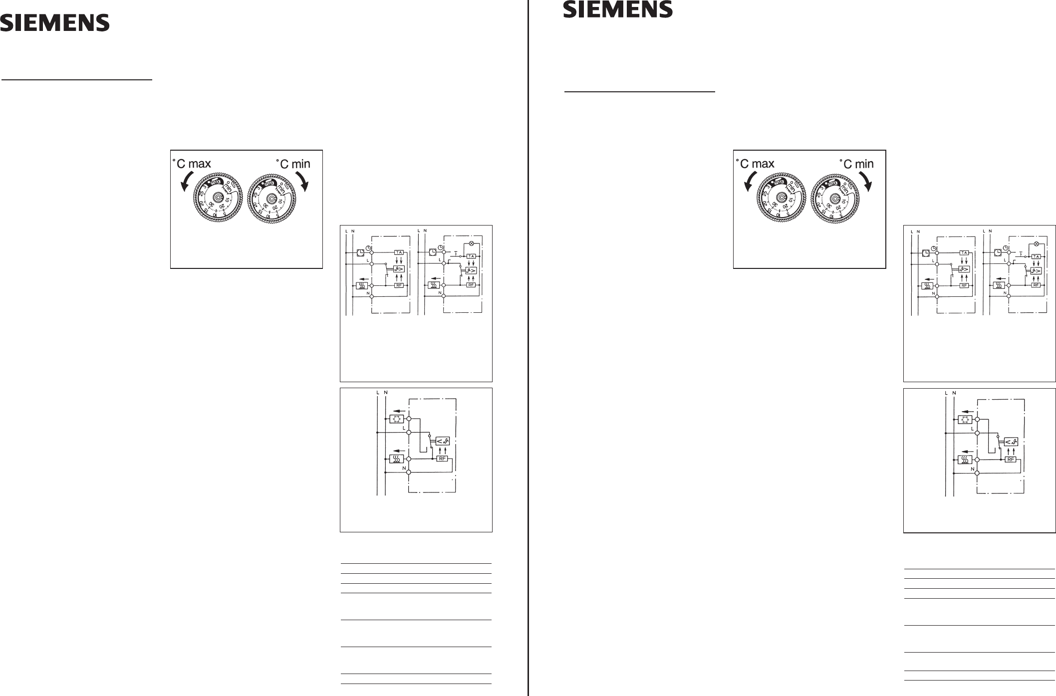
Limiting the temperature
setting range:
The room temperature controller is factory-set
to its full adjustment range of 5 to 30°C (Fig. 1).
There are two adjustment rings on the ad-
justing knob. These enable the temperature
adjustment range to be limited as desired
Mounting:
Location:
The preferred mounting location is on an inner
wall opposite the heating source
●
Mounting height: approximately 1,5 m abo-
ve floor level.
●
Avoid outer walls and drafts from windows
and doors.
●
Ensure that the normal convection currents
of the room can reach the controller unim-
peded. The controller should not be moun-
ted on the wall within shelving or behind
curtains or similar coverings.
●
External heat has an adverse effect on con-
trol accuracy. Avoid direct sunshine and the
immediate vicinity of televisions, radios,
heating appliances, lamps, chimneys and
heating pipes.
●
If fitted in a multi-way carrier, the con-
troller should always be put in the lo-
west position.
●
Combination with dimmers!
If the controller and a dimmer are being
fitted in a common carrier, then a
switch or a socketoutlet must be inter-
posed between the controller and the
dimmer, since the latter is source of
heat.
●
Mounting the controller requires the carriers
of the switching programs DELTA with spe-
cial cut-out.
Mounting in recessed wall box 55
mm (DIN 49 073):
a) Make electrical connections in accordance
with the wiring diagram (Fig. 2).
Ensure that the neutral lead N is
connected to the neutral terminal N. If
this is not done major temperature va-
riations will occur as the controller
cannot function correctly.
The controller is double insulated and does
not require a ground lead.
b) Mount the controller on the wall box with
selftapping screws.
Assembly of colour set
and switch frame
a) Remove protection cap.
b) If applicable attach rocker of switch
c) Mount the cover with switch carrier. Enga-
ge the top left of cover in the base and ins-
ert screw. Push on the adjustment knob.
Wiring diagram symbols:
L = Line
N = Neutral
N
= Connection for time-switch signal for
temperature reduction
U
= Load connection Heating
P
= Load connection Cooling
RF = Resistance for thermal feedback
TA = Resistance for night-time reduction
of room temperature.
Technical data:
Type 5TC9 200 5TC9 201 5TC9 202
Contact Break Changeov. Break
Setting range 5…30°C 5…30°C 5…30°C
Operating voltage AC 250 V AC 250V AC 250V
Switching current
U Heating 10(4)A 10(4)A 10(4)A
P Cooling –– 5(2) A ––
Switching capacity
U Heating 2,2kW 2,2 kW 2,2 kW
P Cooling –– 1,1 kW ––
Hysteresis with ~0,5 K ~0,5 K ~0,5K
thermal feedback
Temp.-setback ~4K – ~4K
Symbole:
(nur für Regler mit 3-Stellungsschalter)
N Automatik (Temperaturabsenkung über
Zeitschaltuhr fernsteuerbar)
L immer Tagestemperatur
M immer abgesenkte Temperatur
Einengen des
Temperatureinstellbereiches:
Werkseitig ist der Raumtemperaturregler auf
den maximalen Einstellbereich von 5 - 30°C
eingestellt (siehe Bild 1).
Im Einstellknopf befinden sich 2 Einstellringe.
Mit diesen kann der Temperatureinstellbe-
reich beliebig eingestellt werden.
Montage:
Montageort:
Ein Installation gegenüber der Heizquelle an
einer Innenwand ist zu bevorzugen.
●
Montagehöhe ca. 1,5m über dem Fußboden.
●
Vermeiden Sie Außenwände und Zugluft
von Fenstern und Türen.
●
Achten Sie darauf, daß die normale Konvek-
tionsluft des Raumes den Regler ungehin-
dert erreicht. Der Regler soll daher nicht in-
nerhalb von Regalwänden oder hinter Vor-
hängen und ähnlichen Abdeckungen mon-
tiert werden.
●
Fremdwärme beeinflußt die Regelge-
nauigkeit nachteilig. Vermeiden Sie daher
direkte Sonneneinstrahlung, die Nähe von
Fernseh-, Rundfunk- und Heizgeräten, Lam-
pen, Kaminen und Heizungsrohren.
●
Bei Anordnung in einem Mehrfachrah-
men ist der Regler stets an die unterste
Stelle zu setzen.
●
Kombination mit Dimmern!
Wird der Regler zusammen mit einem
Dimmer In einem gemeinsamen Schalter-
rahmen montiert, so muß zwischen bei-
den z. B. ein Schalter oder eine Steck-
dose angeordnet sein, da der Dimmer
Wärme erzeugt.
●
Zur Montage der Regler benötigen Sie die
Rahmen der Schalterprogramme DELTA mit
speziellem Ausschnitt.
Montage des Regler-Grundtyps
in Unterputzdose ø 55mm (DIN
49073):
a) Elektrischer Anschluß gemäß Schaltbild
(siehe Bild 2).
Achten Sie darauf, daß der Nulleiter
an die Klemme N angeschlossen wird.
Geschieht das nicht, so ergeben sich
große Temperaturschwankungen, da
der Regler nicht ordnungsgemäß ar-
beiten kann.
Der fertig montierte Regler ist schutziso-
liert, ein Schutzleiteranschluß ist nicht er-
forderlich.
b) Regler mittels gewindeformender UP-
Dosenschrauben auf Dose montieren.
Raumtemperaturregler
Stand April 2002
Bedien- und
Montageanweisung
Die Regler –Grundtypen
5TC9 200
5TC9 201
5TC9 202
sind geeignet für folgende
Schalterprogramme:
DELTA plus
DELTA profil
DELTA style
DELTA ambinte
DELTA i-system
(DELTA vita, DELTA line)
Allgemeine Hinweise:
●
Nach den VDE-Bestimmungen muß die
Montage- und Gebrauchsanweisung jeder-
zeit verfügbar sein und bei Arbeiten am
Gerät dem Monteur zur Kenntnisnahme
übergeben werden. Wir bitten Sie deshalb,
die Anweisung bei Wohnungswechsel dem
Nachmieter oder Besitzer zu übergeben.
●
Der Regler darf nur durch einen Fachmann
installiert bzw. eingesetzt werden. Dabei
sind die bestehenden Sicherheitsvorschrif-
ten zu beachten.
●
Der Raumtemperaturregler ist gemäß VDE
0875 bzw. EN 55014 funkentstört und arbei-
tet nach der Wirkungsweise 1C.
●
Eine zulässige relative Luftfeuchte von max.
95% darf nicht überschritten werden. Be-
tauung ist nicht zulässig.
●
Bei Inbetriebnahme des Raumtemperatur-
reglers ist zu beachten, daß das Thermobi-
metall eine gewisse Zeit benötigt, um sich
der Raumtemperatur anzupassen. Unmittel-
bar nach der Montage wird deshalb der
Schaltpunkt von der Raumtemperatur ab-
weichen. Die Schaltpunktgenauigkeit ist
erst nach ca. 1 bis 2 Stunden Betriebsdauer
gegeben.
Verwendungsbereich:
Der Raumtemperaturregler dient zur Rege-
lung der Temperatur in geschlossenen, trocke-
nen Räumen mit üblicher Umgebung.
Bedienung:
Skala zur Temperatureinstellung mit Merk-
ziffern
PP
entspricht ca. 5°C
2 entspricht ca. 10°C
3 entspricht ca. 15°C
● entspricht ca. 20°C
5 entspricht ca. 25°C
6 entspricht ca. 30°C
468 931 002 982
Bild 1:
Einengen des Temperatureinstellbereiches
5TC9 200
Temperaturabsenkung
über Zeitschaltuhr fern-
steuerbar
Schaltkontakt: Öffner
5TC9 202
Ausführung mit
3-Stellungsschalter
(Automatik, immer
Tagestemperatur,
immer Temperaturab-
senkung)
5TC9 201
Schaltkontakt: Wechsler
Bild 2: Schaltbild
5TC9 200
Normal configuration
with night-time
reduction remotely
controllable via
time-switch
Contact: break
5TC9 202
Configuration with
3-position switch
automatic, (Auto-
matic, constant
daytime setting,
constant night-time
setting)
5TC9 201
change-over contact
Fig. 2: Wiring diagram
Fig. 1:
Limiting the temperature setting range
Irrtum und Änderungen vorbehalten 25 1653.41.01A
Errors possible – Subject to alterations