INBETRIEBNAHME / INITIAL SETUP / MISE EN SERVICE >>
ZUSATZINFORMATION / ADDITIONAL INFORMATION / INFORMATION COMPLÉMENTAIRE
Zweck und bestimmungsgemäße Verwendung:
Die Regelklemmleiste KL 06 wird zur einfachen und sicheren Verbindung von Thermostaten
(bis zu 6 Stück) und elektrischen Geräten (in der Regel Stellantriebe) eingesetzt. Das Pum-
penlogik Modul PL 06 (Zubehör) wird im Zusammenhang mit der Regelklemmleiste KL 06 zur
effektiven Steuerung einer Umwälzpumpe verwendet.
Jeder Thermostat kann bis zu 4 Verbraucher steuern.
Der KL 06 darf ausschließlich in trockenen und geschlossenen Innenräumen montiert wer-
den. Die relative Raumluftfeuchte darf 95% nicht übersteigen.
Das Gerät darf nicht an Stellen montiert werden, wo mit Spritzwasser oder Verschmutzung
durch verunreinigte Luft zu rechnen ist.
Die Regelklemmleiste KL 06 darf nur von ausgewiesenen Elektrofachleuten gemäß dieser
Montageanleitung installiert, geöffnet oder repariert werden. Diese Fachleute sind für die
Beachtung bestehender Normen und Vorschriften verantwortlich.
Die Installation ist immer spannungsfrei durchzuführen, die Sicherheitsvorschriften sind zu
beachten.
Wichtig:
Vor dem Öffnen ist die
Regelklemmleiste
KL 06 von der Spannung zu trennen.
Reinigen Sie das Gerät nur mit einem trockenen, weichen Tuch. Keine Lösungsmittel oder
scharfe Reiniger verwenden!
Für Schäden, die durch Nichtbeachtung dieser Anleitung entstehen, übernimmt
der Hersteller keine Haftung.
Achtung! Jede missbräuchliche Verwendung ist untersagt.
Datenblatt
Operating Voltage 230V / AC
Switching Voltage-Current 24V DC / 230V AC,5A
Dimensions (mm) HxWxL 70 x 75 x 88
Material PC241R
Weight 210 g
Safety Class II
Ambient temperature 0 to 50 °C
Storage temperature -25 to 60 °C
Relative humidity max. 95%
Wiring Requirements:
Solide Wire 0.5-1.5mm
2
Flexible Wire 1.0-1.5mm
2
Purpose and correct use:
Control strip KL 06 is used for simple and safe connection of thermostats (up to six units)
and electrical devices (actuators as a rule). Pump-logic module PL 06 (accessory) is used in
conjunction with the control strip KL 06 for effective control of a circulating pump.
Each thermostat can control up to four consumers.
The KL 06 may be fitted only in dry and closed interior rooms. Relative air humidity in the
room may not exceed 95%.
The appliance may not be mounted in locations where there is a possibility of spraying water
or the presence of contaminated air.
Control strip KL 06 may be installed, opened or repaired only by qualified electricians. These
professionals are responsible for observing existing standards and regulations.
Installation must always be implemented while device is disconnected from the mains, with
due regard for safety regulations.
Important:
disconnect Control Strip K1 06 from mains before opening.
Clean device only with a dry and soft cloth. Do not use solvents or aggressive cleaning
agents!
The manufacturer accepts no responsibility for damage caused by non-observan-
ce of these instructions.
Attention: any improper use is prohibited.
Data specification sheet
Operating Voltage 230V / AC
Switching Voltage-Current 24V DC / 230V AC,5A
Dimensions (mm) HxWxL 70 x 75 x 88
Material PC241R
Weight 210 g
Safety Class II
Ambient temperature 0 to 50 °C
Storage temperature -25 to 60 °C
Relative humidity max. 95%
Wiring Requirements:
Solide Wire 0.5-1.5mm
2
Flexible Wire 1.0-1.5mm
2
But et utilisation conforme :
La barre de réglage à bornes KL 06 est utilisée pour assurer un raccordement simple et sûr
entre les thermostats (six max.) et les appareils électriques (en général des servomoteurs). Le
module de logique pour pompe PL 06 (en option) est utilisé avec la barre de réglage à bornes
KL 06 pour permettre la commande effective d’une pompe de circulation.
Chaque thermostat peut commander jusqu’à quatre récepteurs.
La barre de réglage à bornes KL 06 doit exclusivement être montée dans des locaux secs et
fermés. L’humidité relative de l’air du local ne doit pas dépasser 95 %. .
L’appareil ne doit pas être monté dans des endroits exposés aux éclaboussures ou à un
encrassement par un air vicié.
La barre de réglage à bornes KL 06 doit uniquement être installée, ouverte et réparée par
un électricien qualifié, conformément aux présentes instructions de montage. Il incombe à
l’électricien d’observer les normes et règles en vigueur.
L’installation doit toujours être effectuée hors tension, dans la stricte observation des consi-
gnes de sécurité.
Important :
Mettre la barre de réglage à bornes KL 06 hors tension avant de l’ouvrir.
Ne nettoyez l’appareil qu’avec un chiffon doux et sec. N’utilisez pas de solvants ni de produ-
its nettoyants agressifs !
Le fabricant ne répond pas des dommages provoqués par l’inobservation des
présentes instructions.
Attention ! Toute utilisation abusive est interdite.
Fiche technique
Alimentation en courant
230V / AC
Courant de l‘alimentation
de commutation
24V DC / 230V AC,5A
Dimensions (mm) HxLxl 70 x 75 x 88
Matériau PC241R
Poids 210 g
Classe de protection II
Température ambiante
0 à 50 °C
Température de
stockage
-25 to 60 °C
Humidité relative max. 95%
Cablâge:
Cablâge fixe 0.5-1.5mm
2
Cablâge flexible 1.0-1.5mm
2
1
Regelklemmleiste
Micro Wiring Centre
Barre de réglage à bornes
KL 06
•Klipsen Sie die Basis auf die Service Schiene oder befestigen Sie diese mit Schrau-
ben und Dübeln auf der Wand.
•Click the base onto the service rail or attach them with srews and plugs on the
wall.
•Clippez la base sur la barre de service ou fixez-la au mur à l’aide de vis et de
chevilles.
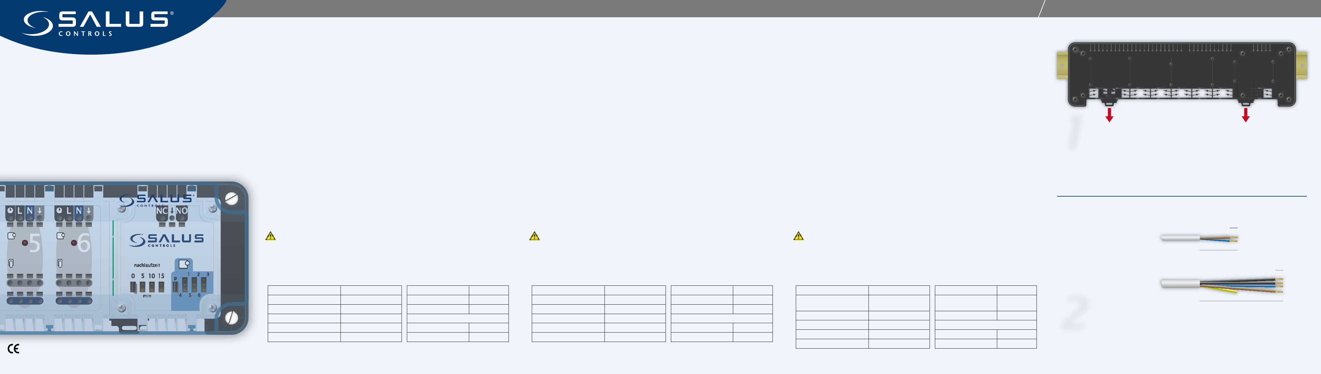
2
•Schneiden Sie die Kabel der Verbraucher, der Thermostate und des Anschlusses
auf die oben angegebenen Längen.
•Cut the cables of the devices, the thermostates and the mains cable to the length
mentionned above.
•Couper les câbles des dispositifs, des thermostates et de la puissance principale
câbler au lenght mentionné ci-dessus.
50 mm
10 mm
110 mm
10 mm
Verbraucher
Device
Récepteurs
Thermostat / Anschluss / Pumpe
Thermostate / Power / Pump
Thermostate / Raccord / Pompe