4
UNPACKING INSTRUCTION
CAUTION! Immediately upon receiving the product, carefully unpack the carton, check the contents to ensure that all parts are
present, and have been received in good condition. Notify the shipper immediately and retain packing material for inspection if
any parts appear damage from shipping or the package itself shows signs of mishandling. Save the package and all packing
materials. In the event that the product must be returned to the factory, it is important that the product be returned in the original
factory box and packing.
If the device has been exposed to drastic temperature fluctuation (e.g. after transportation), do not switch it on immediately. The
arising condensation water might damage your device. Leave the device switched off until it has reached room temperature.
POWERSUPPLY
On the label on the backside of the product is indicated on this type of power supply must be connected. Check that the mains
voltage corresponds to this, all other voltages than specified, the product be irreparably damaged. The product must also be
directly connected to the mains and may be used. No dimmer or adjustable power supply.
Always connect the device to a protected circuit (circuit breaker or fuse). Make sure the device has an appropriate
electrical ground to avoid the risk of electrocution or fire.
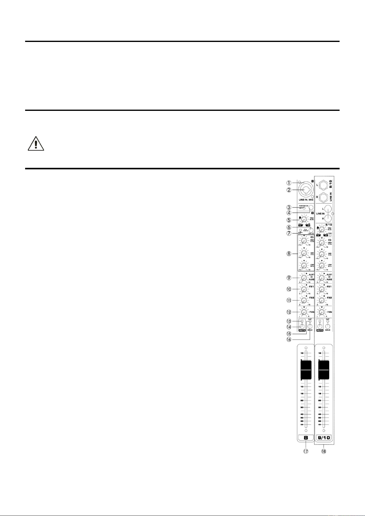
CONTROL ELEMENTS
1. Microphone Input
Balanced XLR input jacks.
2. Line Input
Balanced 6.3mm (¼”) jack line inputs. You can connect either balanced or unbalanced phone
plugs to these jacks.
3. 48V indicator
The red LED lights up when phantom power is switched on. Phantom power is required to
operate condenser microphones.
4. Phantom +48V
This switch toggles phantom power on and off. When the switch is on the mixer supplies +48V
phantom power to all channels that have XLR input jacks. Turn this switch on when using one
or more phantom-powered condenser microphones.
5. TRIM Control
Adjusts the input signal level. To get the best balance between the S/N ratio and the dynamic
range, adjust the gain so that the peak indicator (15) lights only occasionally and briefly on the
highest input transients. The -60 to +10 scale is the MIC input adjustment range. The 40 to
+10 scale is the line input adjustment range.
6. Low Out Switch
This switch toggles the HPF on or off. To turn the HPF on, the HPF cuts frequencies below
75Hz.
7. Signal LED Indicator
Check the input signal.
8. Equalizer
Three-band equalizer adjusts the channel's high, mid and low frequency bands. Setting the
knob to the "O" position produces a fiat response in the corresponding band. Turning the knob
to the right boosts the corresponding frequency band, while turning to the left attenuates the
band.
9. Aux Control
Monitor and effect busses (Aux sends) source their signals via a control from one or more
channels and sum these signals to a so-called bus. This bus signal is sent to an aux send
connector (for monitoring applications: Mon Out) and then routed, for example, to an active
monitor speaker or external effect device. In the latter case, the effects return can then be
brought back into the console via the aux return connectors. All monitor and effect busses are
mono, are tapped into post EQ and offer amplification of up to +15dB.
10. FX1 Control
The aux send marked FX offers a direct route to the built-in effects processor and is therefore
post-fader and post-mute.
11. FX2 Control
The aux send marked FX offers a direct route to the built-in effects processor and is therefore
post-fader and post-mute.
12. PAN Control
The PAN control determines the position of the channel signal within the stereo image. When
working with subgroups, you can use the PAN control to assign the signal to just one output,
which gives you additional flexibility in recording situations.
13. Mute LED
The mute LED indicates a muted channel.