Nota:
• Antes de finalmente instalar la unidad, conecte el
cableado temporalmente y asegúrese de que todo
esté conectado correctamente y que la unidad y
el sistema funcionan debidamente.
• Utilice sólo las piezas que se incluyen con esta
unidad para asegurar la instalación adecuada. El
uso de piezas no autorizadas podría causar fallos
de funcionamiento.
• Consulte con su distribuidor si la instalación
requiere del taladro de orificios u otras modifica-
ciones del vehículo.
• Instale la unidad donde no alcance el espacio del
conductor, y donde no pueda dañar a los
pasajeros si sucediera un paro repentino, como
una detención de emergencia.
• El semiconductor láser se dañará si se sobre-
calienta, por eso no instale la unidad en un lugar
caliente – por ejemplo, cerca de la salida de un
calefactor.
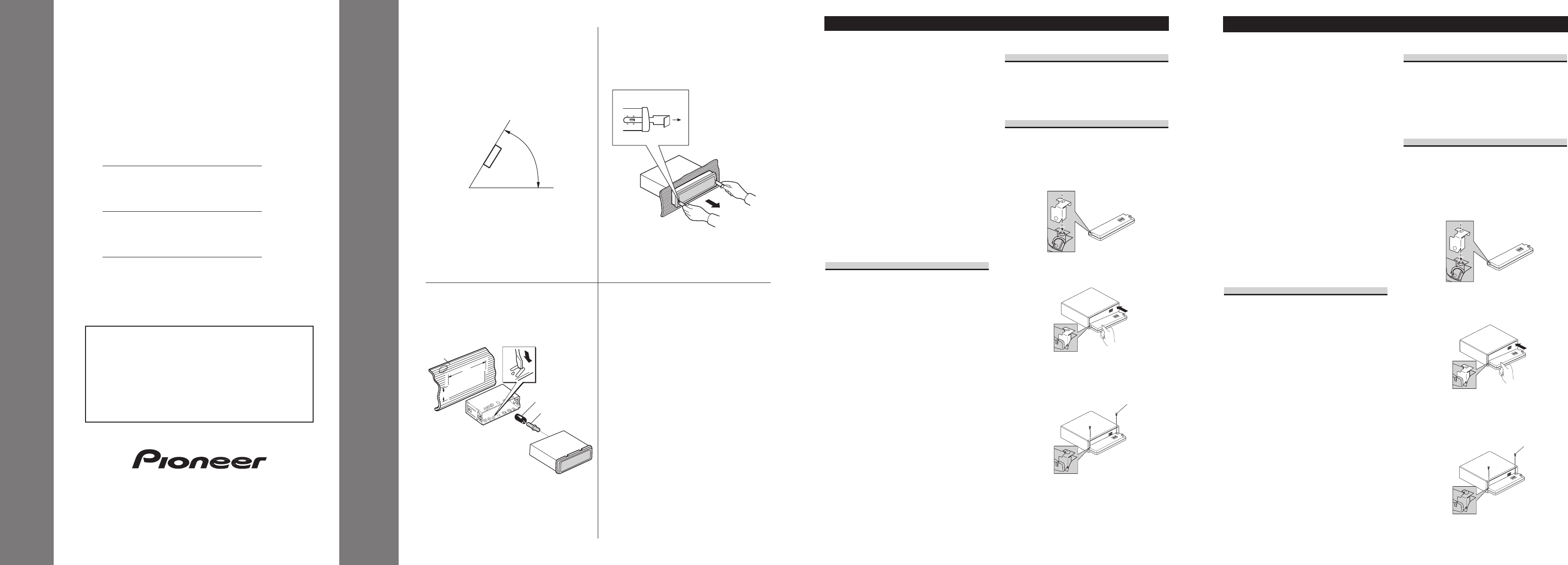
• Si el ángulo de la instalación excede los 60° del
lado horizontal, la unidad podría no brindar su
óptimo funcionamiento. (Fig. 1)
Instalación con tope de goma
(Fig. 2)
1. Tablero de instrumentos
2. Soporte
Después de insertar el soporte en la tabla de
mandos, luego seleccione las orejetas apropiadas
según el grosor del material de la tabla de man-
dos y dóblelos.
(Instale lo más firme posible usando las lengüe-
tas superior e inferior. Para fijar, doble las
lengüetas 90 grados.)
3. Tope de goma
4. Tornillo
Quitado de la unidad (Fig. 3)
5. Inserte las herramientas de extracción suminis-
tradas en la unidad, como se indica en la figura,
hasta que se enganchen en su positión.
Tire de la unidad mientras mantiene las her-
ramientas presionadas contra los lados de la
unidad.
Colocación del panel delantero
Si no desea utilizar la función de extracción y
colocación del panel delantero, utilice los tornil-
los de fijación suministrados y fije el panel
delantero a esta unidad.
1.
Coloque lo sujetadore en el panel
delantero.
2. Reinstale el panel delantero en la
unidad.
3. Fije el panel delantero a la unidad
utilizando los tornillos de fijación.
Instalación <ESPAÑOL>
Note:
• Before finally installing the unit, connect the
wiring temporarily, making sure it is all connect-
ed up properly, and the unit and the system work
properly.
• Use only the parts included with the unit to
ensure proper installation. The use of unautho-
rized parts can cause malfunctions.
• Consult with your nearest dealer if installation
requires the drilling of holes or other modifica-
tions of the vehicle.
• Install the unit where it does not get in the dri-
ver’s way and cannot injure the passenger if there
is a sudden stop, like an emergency stop.
• The semiconductor laser will be damaged if it
overheats, so don’t install the unit anywhere hot
— for instance, near a heater outlet.
• If installation angle exceeds 60° from horizontal,
the unit might not give its optimum performance.
(Fig. 1)
Installation with the rubber bush
(Fig. 2)
1. Dashboard
2. Holder
After inserting the holder into the dashboard,
then select the appropriate tabs according to the
thickness of the dashboard material and bend
them.
(Install as firmly as possible using the top and
bottom tabs. To secure, bend the tabs 90
degrees.)
3. Rubber bush
4. Screw
Removing the Unit (Fig. 3)
5. Insert the supplied extraction keys into the unit,
as shown in the figure, until they click into place.
Keeping the keys pressed against the sides of the
unit, pull the unit out.
Fixing the Front Panel
If you do not operate the Removing and
Attaching the Front Panel Function, use the sup-
plied fixing screws and fix the front panel to this
unit.
1.
Attach the holder to the front panel.
2. Replace the front panel to the unit.
3. Fix the front panel to the unit using
fixing screws.
Installation <ENGLISH>
INSTALLATION MANUAL
MANUEL D’INSTALLATION