1) For this purpose connect a desk microphone
PA-1120PTT (see chapter 6.3).
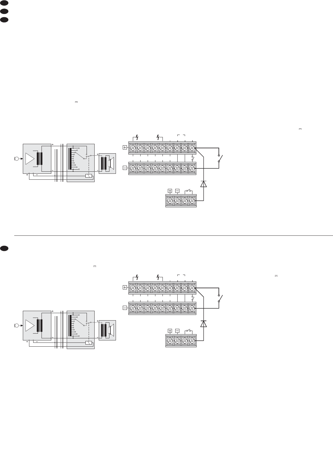
2) Connect the emergency priority relays according
to fig. 5 to the screw terminals 24 V /0,2 A
MAX
(43). The output allows a load of 200 mA.
3) Set the switch PRIORITY (47) on the micro-
phone to position ON (downwards).
4) Upon actuation of the TALK button (49), the
speakers are now switched to maximum volume
via the relays.
Emergency priority relays
6.10 Switch for (automatic) announcements
in all zones
For the remote control of the following functions
connect a switch to the terminals MESSAGE FIRST
PRIORITY (33).
1. All PA zones are switched on and set to maxi-
mum volume [like button ALL CALL (6)].
2. When using the digital message insertion PA-
1120DM, the announcement of storage M 6 is
automatically called. For this purpose, set the
jumper MS 2 to position PRI prior to installing the
insertion (see layout diagram on page 42). Thus,
the announcement of the memory M 6 takes first
priority.
Instead of the switch, an alarm contact may
be connected, e. g. for an automatic fire alarm
announcement.
3. If the amplifier is to be switched on simul taneously
via the switch or the alarm contact, insert a diode
of type 1N4004 between the upper terminal MES-
SAGE FIRST PRIORITY and the right terminal
POWER REMOTE according to fig. 6.
Automatic switching on of the amplifier and
activation of the announcement M 6
6.11 Telephone switchboard
From a telephone switchboard, announcements
may be reproduced via the PA system.
1) Feed the telephone signal (line level) to the ter-
minals PAGING IN (32).
2) During an announcement, adjust the volume with
the control PAGING (15).
Note: Telephone announcements take 3
rd
priority.
6.12 Activation/deactivation by remote control
A separate switch allows to switch the amplifier on
and off by remote control.
1) Connect the screw terminals POWER REMOTE
(31) via a two-pole cable to a single-pole power
switch.
2) For activation/deactivation by remote control, the
main switch POWER (24) must not be pressed.
6.13 Power supply and
emergency power supply
1) For continuous operation of the amplifier after
power failure connect a 24 V emergency power
supply unit (e. g. PA-24ESP from MONACOR) to
the terminals 24 V (30). For a cable length of
up to 7 m a cable cross-section of 4 mm
2
as a
minimum is required.
2) Finally connect the supplied mains cable to the
mains jack (27) first and then to a mains socket
(230 V~/50 Hz).
Note: Even if the amplifier is switched off, it con -
sumes a low power. Therefore, disconnect the
mains plug from the socket and, if necessary, dis-
connect the emergency power supply unit if the
amplifier will not be in operation for a longer time.
10
GB
D
A
CH
3) Die Klingel auslösen und mit dem Regler RIN-
GER (16) die Lautstärke des vom Verstärker
erzeugten Rufzeichens einstellen.
4) Die Ruffunktion mit der Taste TEL je nach Bedarf
ein- oder ausschalten.
Hinweis: Die Klingel hat niedrigste Priorität.
6.9 Pflichtempfangsrelais
Sind zwischen dem Verstärker und den Lautspre-
chern ELA-Lautstärkeeinsteller mit Pflichtempfangs-
relais (z. B. Serie ATT-3..PEU oder ATT-2..P/WS
von MONACOR) geschaltet, können wichtige Durch-
sagen auch bei eingestellter Laut stärke „Null“ gehört
werden.
1) Dazu ein Tischmikrofon PA-1120PTT anschlie -
ßen (siehe Kap. 6.3).
2) Die Pflichtempfangsrelais nach der Abb. 5 an
die Schraubklemmen 24 V /0,2 A
MAX (43) an -
schlie ßen. Der Ausgang ist mit 200 mA belastbar.
3) Am Mikrofon den Schalter PRIORITY (47) in die
Position ON (nach unten) stellen.
4) Beim Betätigen der Sprechtaste TALK (49) wer-
den jetzt durch die Relais die Lautsprecher auf
maximale Lautstärke geschaltet.
Pflichtempfangsrelais
6.10 Schalter für (automatische) Durchsagen
in allen Zonen
Zur Fernsteuerung der folgenden Funktionen einen
Schalter an die Klemmen MESSAGE FIRST PRIO-
RITY (33) anschließen:
1. Alle Beschallungszonen werden eingeschaltet
und auf maximale Lautstärke gestellt [wie Taste
ALL CALL (6)].
2. Bei Verwendung des Digital-Message-Einschubs
PA-1120DM wird automatisch die Durchsage
des Speichers M 6 abgerufen. Dazu die Brücke
MS 2 vor dem Einbau des Einschubs in die Posi-
tion PRI stellen (siehe Lageplan auf Seite 42).
Dadurch erhält die Durchsage des Speichers
M 6 erste Priorität.
Anstelle des Schalters kann auch ein Alarm-
meldekontakt angeschlossen werden, z. B. für
eine automatische Feueralarmdurchsage.
3. Soll durch den Schalter bzw. durch den Alarmmel-
dekontakt der Verstärker auch gleichzeitig einge-
schaltet werden, eine Diode vom Typ 1N4004
nach Abb. 6 zwischen die obere Klemme MES-
SAGE FIRST PRIORITY und die rechte Klemme
POWER REMOTE schalten.
Automatisches Einschalten des Verstärkers und
Aktivieren der Durchsage M 6
6.11 Telefonzentrale
Von einer Telefonzentrale lassen sich Durchsagen
über die ELA-Anlage wiedergeben.
1) Das Telefonsignal (Line-Pegel) auf die Klemmen
PAGING IN (32) geben.
2) Während einer Durchsage mit dem Regler
PAGING (15) die Lautstärke einstellen.
Hinweis: Telefondurchsagen haben 3. Priorität.
6.12 Ferngesteuertes Ein- und Ausschalten
Der Verstärker lässt sich über einen separaten
Schalter ferngesteuert ein- und ausschalten.
1) Die Schraubanschlüsse POWER REMOTE (31)
über eine zweipolige Leitung mit einem einpoli-
gen Ein-/Ausschalter verbinden.
2) Zum ferngesteuerten Ein- und Ausschalten darf
der Hauptschalter POWER (24) nicht gedrückt
sein.
6.13 Strom- und Notstromversorgung
1) Soll der Verstärker bei einem Netzausfall weiter-
arbeiten, an die Klemmen 24 V (30) eine 24-V-
Notstromeinheit (z. B. PA-24ESP von MONACOR)
anschließen. Bei einer Kabellänge von bis zu 7 m
ist ein Kabelquerschnitt von mindestens 4 mm
2
erforderlich.
2) Zum Schluss das beiliegende Netzkabel zuerst
in die Netzbuchse (27) und dann in eine Steck-
dose (230 V~/50 Hz) stecken.
Hinweis: Auch wenn der Verstärker ausgeschaltet
ist, verbraucht er einen geringen Strom. Darum den
Netzstecker aus der Steckdose ziehen und ggf. die
Notstromeinheit abklemmen, wenn der Verstärker
längere Zeit nicht betrieben wird.