Battery
Compartment
Remove the covers of the battery compartments
located on the fork arms (one on each fork arm) and
carefully lift the battery holders from their compartments,
being mindful of the connector wires. Insert four (user-
supplied) C-cell batteries into each battery holder, oriented
as shown on the diagram on the battery holder. Return the
battery holders to their respective compartments. Replace
the covers when you are done.
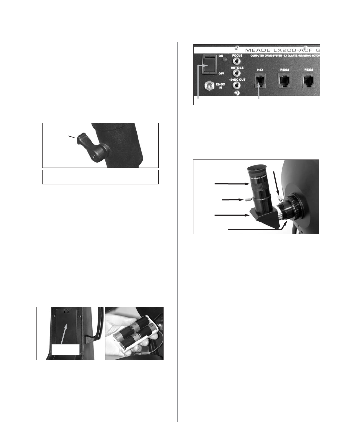
Press the computer control panel power switch to
OFF, if necessary. Remove the AutoStar II handbox and
the AutoStar II coil cord from the packing materials. Plug
one end into the HBX port of the telescope’s computer
control panel and plug the other end into the coil cord port
on the AutoStar II handbox.
ON/OFF
HBX Port
- 5 -
Move the spreader bar so that the 3 arms of the spreader
bar are lined up with the 3 tripod legs. Place the entire
telescope onto the top of the tripod head, and thread the
rod into the central threaded hole in the bottom of the drive
base of the telescope. Tighten the T-handle tension knob
(Fig. A, 3); firm tightening of the tension knob is sufficient
to result in rigid positioning of the tripod legs. It is not
necessary to use extreme force in tightening this
knob.
To vary the tripod height, loosen the 3 leg lock-levers and
slide the 3 inner tripod leg sections out to the desired
height. Retighten the 3 lock-lever to a firm feel (Fig. F).
To collapse the tripod (after removing the telescope),
rotate the spreader bar 60° from its assembled position, so
that one spreader bar arm is located between each
adjacent pair of tripod legs. At the base of the tripod is a 3-
vane extension strut system, with a circular hub at its
center (Fig. A, 7). Grasp the tripod head (Fig. A, 1) with
one hand and, with the other hand, pull directly “up” on the
central hub of the extension strut system. This operation
will cause the tripod legs to move inward to a collapsed
position.
CAUTION: If the tripod does not seem to extend or
collapse easily, do not force the tripod legs in or
out. By following the instructions above, the
tripod will function properly, but if you are unclear
on the proper procedure, forcing the tripod into an
incorrect position may damage the extension
strut system.
Attach the 1.25" Diagonal (8", 10", 12" and 14"
Models Only): Remove the dust cap from the rear cell of
the telescope. Thread the eyepiece holder into the rear
cell thread. Slide the diagonal prism into the eyepiece
holder and lock in place by turning the thumbscrew to a
firm feel.
Place the Super Plössl 26mm eyepiece into the diagonal
prism and tighten the attachment thumbscrew to a firm
feel only.
Thumbscrew
Thumb-
screw
Fig. F: Loosen leg lock lever, extend inner
extendable leg, and re-lock lock lever.
lock-lever
Rear Cell Port
Eyepiece
Diagonal
Prism