785578
1
Zoom out
Zoom in
Previous page
1/2
Next page
Mastervolt International B.V. P.O.Box 22947, NL-1100 DK Amsterdam, The Netherlands. Tel.: +31-20-3422100 Email: info@mastervolt.com Web: www.mastervolt.com October 2003
NEDERLANDS
Productbeschrijving en toepassing
Mastervolt laadstroomverdelers dienen voor de verdeling van de laadstroom tussen meerdere
accugroepen van dezelfde nominale spanning. Door toepassing van een laadstroomverdeler wordt
voorkomen dat de accugroepen elkaar kunnen ontladen. Mastervolt laadstroomverdelers zijn
uitsluitend geschikt voor installatie tussen de positieve uitgang van de voedingsbron (bijvoorbeeld een
acculader of een dynamo) en de positieve aansluitingen van de accugroepen. Hierbij dienen de
negatieve uitgang van de voedingsbron en de negatieve aansluitingen van de accugroepen direct met
elkaar te worden doorverbonden. De laadstroomverdelers zijn niet geschikt voor toepassing met een
gecombineerde acculader/omvormer (combi).
Installatie
Overtuig uzelf ervan dat de uitgang van de voedingsbron spanningsloos is gedurende de
installatiewerkzaamheden. Zorg er tevens voor dat er geen gebruikers zijn aangesloten op de
accugroepen ter voorkoming van onveilige situaties.
Monteer de laadstroomverdeler zo dicht mogelijk bij zowel de voedingsbron als bij de accugroepen. De
laadstroomverdeler kan warm worden als gevolg van grote stromen. Installeer de laadstroomverdeler
daarom op een goed geventileerde plaats, bij voorkeur op een vlakke metalen ondergrond, met de
koelribben verticaal geplaatst.
Aansluiten
Sluit de laadstroomverdeler als volgt aan (zie tekening voor de juiste wijze van aansluiten):
1. Sluit de positieve uitgang van de voedingsbron aan op de A-aansluiting van de laadstroomverdeler.
De A-aansluiting is de langste bout.
2. Sluit de positieve aansluitingen van de accugroepen aan op respectievelijk 1, 2 en eventueel 3.
3. Alleen bij modellen met compensatiediode-aansluiting (702 S, 1202 S en 1203 S): Sluit de sense-
aansluiting van de voedingsbron aan op de S-aansluiting van de laadstroomverdeler. De S-
aansluiting is de dunste bout.
4. Monteer de negatieve aansluitingen van de accugroepen en de voedingsbron op een
gemeenschappelijk massapunt.
Bij modellen zonder compensatiediode-aansluiting dient u de uitgangsspanning van de voedingsbron
aan te passen om de spanningsval door de laadstroomverdeler (ca. 0,7V) te compenseren. Zie hiertoe
de handleiding van de voedingsbron. Bij gebruik van een laadstroomverdeler met een
compensatiediode-aansluiting (S-types) dient u de uitgangsspanning van de voedingsbron NIET te
verhogen: de juiste uitgangsspanning van de laadstroomverdeler wordt automatisch geregeld middels
de sense-aansluiting S.
Veiligheidsvoorschriften en –maatregelen
1. Installeer de laadstroomverdeler volgens bovengenoemde instructies
2. Gebruik de laadstroomverdeler nooit op een locatie met gas- of stofontploffingsgevaar.
3. Aansluitingen en beveiligingen moeten overeenkomstig de plaatselijk geldende voorschriften
worden uitgevoerd.
4. Gebruik kabels met voldoende draaddoorsnee en houd alle afstanden zo kort mogelijk. Gebruik
deugdelijke kabelschoenen en draai alle aansluitmoeren goed aan. (zie ‘nut instruction’)
Garantiebepalingen
Mastervolt garandeert dat de laadstroomverdeler zijn geproduceerd volgens de wettelijk van
toepassing zijnde normen en bepalingen. Gedurende de productie en voor aflevering zijn alle
laadstroomverdelers uitvoerig getest en gecontroleerd. Wanneer niet volgens de in deze handleiding
gegeven voorschriften, aanwijzingen en bepalingen wordt gehandeld, kunnen beschadigingen
ontstaan en/of het apparaat zal niet aan de specificaties voldoen. Een en ander kan inhouden dat de
garantie komt te vervallen.
De garantietermijn is twee jaar.
Aansprakelijkheid
Mastervolt kan niet aansprakelijk worden gesteld voor:
Schade ontstaan door het gebruik van de laadstroomverdeler
Eventuele fouten in bijbehorende handleiding en de gevolgen daarvan
Ander gebruik geldend als niet conform de bestemming van het product
TECHNICAL SPECIFICATIONS
CONNECTIONS
Connections
Part number Model Max output
charger
Max output
alternator Input Outputs Sense
83-00-7030* BI703 25/50 A 70 A A 1, 2, 3
83-00-7020* BI702 25/50 A 70 A A 1, 2
83-00-7021** BI702 S 25/50 A 70 A A 1, 2 S
83-01-2030* BI1203 80 A 120 A A 1, 2, 3
83-01-2031** BI1203 S 80 A 120 A A 1, 2, 3 S
83-01-2020* BI1202 80 A 120 A A 1, 2
83-01-2021** BI1202 S 80 A 120 A A 1, 2 S
* models without compensation diode ** models with compensation diode
GENERAL
Input voltage 6-50 VDC
Insulation to ground >500V @ 60Hz
Operation temperature -40 to +120°C
Voltage drop 0,7V (approximately)
COMPLIANCE
CE yes
ENGLISH
Product description and application
Mastervolt battery isolators are designed to distribute the charge current between several (sets of)
batteries with the same nominal voltage. The battery isolator prevents the current from flowing from
one battery to another. Mastervolt battery isolators can only be installed in the positive lead between
the supplying source (for instance a charger or an alternator) and the batteries. Therefore the negative
output of the supplying source should be connected directly to the negative connections of the battery
sets. The battery isolator cannot be used in combination with a combined charger / inverter (combi).
Installation
Be sure that the output of the supplying source is switched off during installation. Also be sure that no
consumers are connected to the batteries during installation, to prevent hazardous situations.
Install the battery isolator not only as close as possible to the supplying source, but to the batteries as
well. The battery isolator must be installed in a well-ventilated environment, as high currents will heat
up the battery isolator. Preferably, the battery isolator should be mounted on a flat metal surface, with
the fins vertical.
Connections
To connect battery isolator, proceed as follows (see drawing for the correct connections):
1. Connect the positive output of the supplying source to the A-connection of the battery isolator. The
A-connection is the tallest bolt.
2. Connect the positive connection of the battery sets to connections 1, 2 and optional 3 respectively.
3. Only for models with connection for diode compensation (702 S, 1202 S and 1203 S): Connect the
sense-connection of the supplying source to the S-connection of the battery isolator. The S-
connection is the slimmest bolt.
4. Connect the negative poles of the battery sets and the supplying source to a common ground.
If a battery isolator without diode compensation is used, the output voltage of the supplying source
should be adjusted to compensate the voltage drop over the battery isolator (circa 0,7V). Please refer
to the user manual of the supplying source. If a battery isolator with diode compensation is used (S-
types), the output voltage of the supplying source should NOT be increased for diode compensation:
the output voltage of the battery isolator is adjusted automatically by means of the voltage sense
connection S.
Safety regulations and measures
1. Install the battery isolator according to the stated instructions.
2. Never use the battery isolator at a location where there is danger of gas or dust explosions.
3. Connections and safety features must be executed according to the locally applicable regulations.
4. Use cables with appropriate size wire and keep the cable connections as short as possible. Use
reliable terminals and fasten the bolts tightly, but do not over torque (also see ‘nut instruction’).
Guarantee terms
Mastervolt guarantees that the battery isolators have been built according to the legally applicable
standards and stipulations. During production and before delivery all battery isolators were
exhaustively tested and controlled. If you fail to act in accordance with the regulations, instructions and
stipulations of this user’s manual, damage can occur and/or the unit will not fulfil the specifications.
This may mean that the guarantee will become null and void.
The guarantee period is 2 years.
Liability
Mastervolt cannot be held liable for:
Damage resulting from the use of the battery isolator.
Possible errors in the included manual and the consequences of these.
Use that is inconsistent with the purpose of the product.
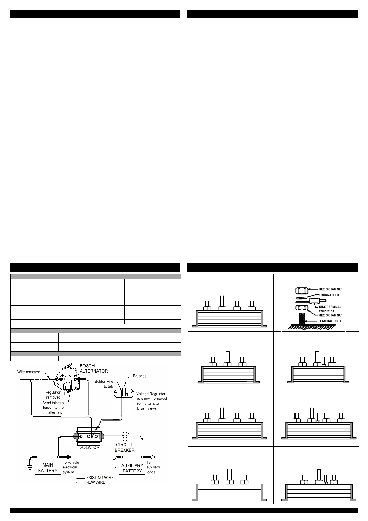
CONNECTIONS BATTERY ISOLATOR
BI 703 NUT INSTRUCTION
BI 702 BI 702 S
BI1203 BI 1203 S
BI 1202 BI 1202 S
Typical connection diagram of a Mastervolt Battery-isolator with diode compensation (-S
types) in combination with a Bosch alternator. Please refer to the installation manual of
your alternator if any other alternator is used.
1 A S 2 1 A 2
1 A S 2 3 1 A 2 3
1 A 2 3
1 A 2 1 A S 2
1 A S 2
1


Need help? Post your question in this forum.

Forumrules


Report abuse

Libble takes abuse of its services very seriously. We're committed to dealing with such abuse according to the laws in your country of residence. When you submit a report, we'll investigate it and take the appropriate action. We'll get back to you only if we require additional details or have more information to share.

Product:

For example, Anti-Semitic content, racist content, or material that could result in a violent physical act.

For example, a credit card number, a personal identification number, or an unlisted home address. Note that email addresses and full names are not considered private information.

Forumrules

To achieve meaningful questions, we apply the following rules:

Register

Register getting emails for Mastervolt Laadstroomverdeler BI 1202-S at:


You will receive an email to register for one or both of the options.


Get your user manual by e-mail

Enter your email address to receive the manual of Mastervolt Laadstroomverdeler BI 1202-S in the language / languages: English, German, Dutch, French, Italian, Spanish as an attachment in your email.

The manual is 0.16 mb in size.


You will receive the manual in your email within minutes. If you have not received an email, then probably have entered the wrong email address or your mailbox is too full. In addition, it may be that your ISP may have a maximum size for emails to receive.

The manual is sent by email. Check your email

If you have not received an email with the manual within fifteen minutes, it may be that you have a entered a wrong email address or that your ISP has set a maximum size to receive email that is smaller than the size of the manual.

The email address you have provided is not correct.

Please check the email address and correct it.

Your question is posted on this page

Would you like to receive an email when new answers and questions are posted? Please enter your email address.


Info