Master P.O.Box 22947, NL-1100 DTel.: +Email: info@mastervolt.com Web www.mastervolt.com J
NEDERLANDS
Productbeschrijving en toepassing
De Mastervolt Bat
• Onderspanning: de
belasting wordt pas
low.on). Door ee
spanningsvall
• Overspanning: d
ingeschakeld zodr
De Battery
Installatie
Overtuig uz
installatiewerkz
accugroepen ter voorkoming
De Battery
op een goed gev
verticaal geplaatst. Monteer ery de accu, maar nooit dire
een accu i.v.m. mogelijke corrosie
Aansluiten
Zie tekening (“i
de accugroepen e
Monteer een schakel
hoofdschakelaar v
Instellingen
De Battery Watch detecteert aut
Aan de bovenz
onderspanningniveau. Gebruik een kleine sch de instelling
“DIP-settings” voor instellingen.
Indien DIP-switches 1,2 en 3 tegelijkertijd op ‘ON’ staan ingeste
onderspanningen.
Veiligheidsvoorschriften en –maatregelen
1. Installeer de Batter
2. Gebruik de Battery
3. Aansluitingen en beveiligingen moet
voorschriften w
4. Gebruik kabels met voldoende dra
deugdelijke kabelschoenetmoeren g
Garantiebepalingen
Mastervolt garandeert dat de Battery s de wettelijk van toep
zijnde normen
getest en gecontr
aanwijzing
niet aan de speci
De garantietermijn is t
Aansprakelijkheid
Mastervolt kan niet aansprakelijk w
• Schade ontstaan do
• Eventuele fouten
• Ander gebruik g
INSTALLATION
ENGLISH
Product description and applicati
The Mastervolt Batter
• Under voltage: th
reconnected again w
a 30 seconds switching delay, the Battery Watch will not respond to short voltage dips.
• Over voltag
when the batter
The Battery
ground
Installation
Be sure that the
consumers are connec
Install the Batter
well, but do not
sulphur fumes. The
will heat up the
surface with the
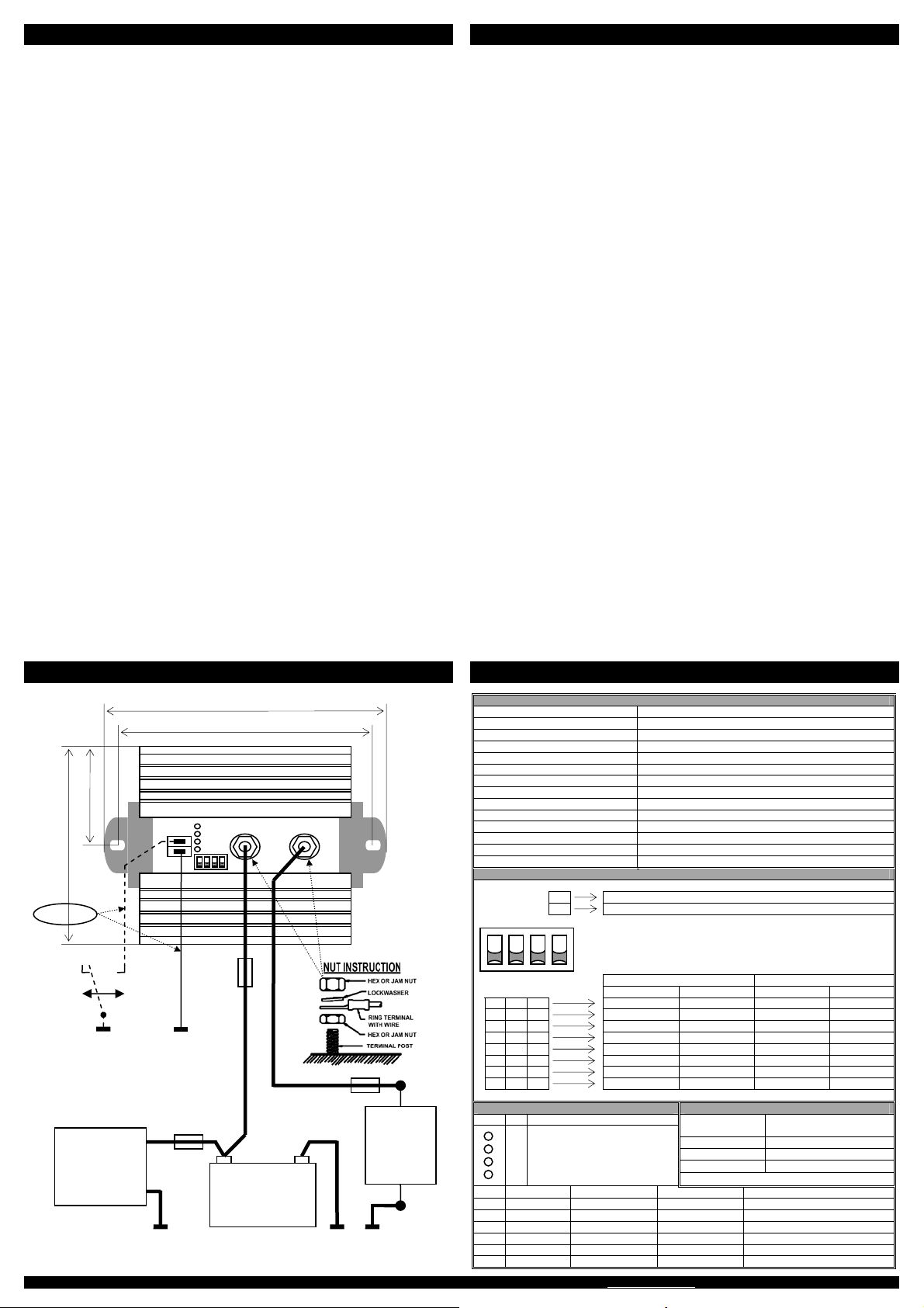
Connections
For correct connecti
the supplying
Connect a switch b
Battery
Adjus
The Battery
On top of the Batter
“DIP-settings” tabl
If DIP-switches 1,
voltages. If DIP-switch 4 is sw
Safety regulations and measu
1.
2.
3.
4.
reliable terminals
Guarantee terms
Mastervolt guarante
standards and sti
and controlled. I
user’s manual, damage ca
the guarantee will becom
The guarantee period is 2 y
Liability
Mastervolt cannot b
• Damage resulting fro
• Possible errors i
• Use that is inconsistent w
BATTERY WATCH
SPECIFICAT
Article number 83 20 0150
Input Voltage 8 – 32V
Switch OFF under v 9.0V…12.0V or 18.
Switch ON under v 10.5V…13.0V or 2
Switch OFF over v 15.5V or 31.0V (
Switch ON over 15.0V or 30.0V (
Delay high v 1 sec.
Delay high v 10 sec.
Delay low voltage OFF 30 sec.
Delay low voltage ON 10 sec.
Nominal Cur 100A
Maximum Curre 150A
Voltage drop <0.2V
Remote main sw Single pole, on-o
DIP SETTINGS
0 Audible
1 Audible al
Ç
1 ON
0 OFF
1 2 3 4 U-bat = 12V U-bat = 24V
È È È U-lo U-low.off U-low.on
10.5
11.0
LED INDICATIONS RECOMMENDED WIRE SIZES
LED # DC-Current Wire size (up to 3 meters)
50-75 Amp 25 mm² (AWG 3)
75-100 Amp 35 mm² (A
100-150 Amp 50 mm² (AWG 0)
1
2
3
4
Power
High battery
Low battery
Overload
LED: 1 2 3 4
On Over voltag Under voltage Overload
Aan Overspanning Onderspanning Overbelasting
Ein Überspannung Unterspannung
Marche Sur-tension Sous-tensio Surcharge
On Sov Bassa
On Sobr Subtensión Sobrec
+ –
Battery Accu
Akku Batter
Batteria Batterí
Battery charg
Acculader
Akkulader
Chargeur
Caricabatterie
Cargador
+
Load
Belasting
Last
Charge
Carico
Carga
Off
Uit
Aus
Arrêt
On
Aan
Ein
Marche
Ø 0,5 mm²
157 mm
140 mm
140 mm
70 mm
+
–
1 2 3 4
Remote main switch
Bediening als hoo
Fernbedienung H
Télécommande d’
Commando interr
Remoto desconact