ENGLISH
10
ENGLISH
11
AVT150/AVT150H & AVT275 Front Panel Features
AVT150 & AVT150H Rear Panel Features
23 DFX Mix Controls
(Clean FX & Overdrive FX)
These determine the level of the internal
effects selected by the pair of Program controls
(25). The top DFX Mix control works on the
two OD channels while the bottom one works
on the Acoustic Simulator and Clean channels.
In general you will find that the modulation
effects (e.g. Chorus, Flange) require more level
than the reverbs and delays. As always, let
your ears decide what is right!
24 Adjust Controls
(Clean FX & Overdrive FX)
For each of the 16 selectable DFX a
particular parameter is adjustable. For
example, when a Reverb is chosen, the decay
(how long the reverb will be heard before it
fades away) is adjustable via this control. The
‘Program/Adjust’ table (26) on the front panel of
your amp lists what the Adjust control does for
each of the 16 programs. As was the case with
the DFX Mix controls, the top Adjust control
works for the two OD channels and the bottom
one for the Clean & Acoustic Simulator
channels.
25 Program
(Clean FX & Overdrive FX)
These select each one of the 16 on board
digital effects - the top Program control works
on the two OD channels and the bottom control
works for the Clean and Acoustic Simulator
Channels. The DFX available include single
effects such as Reverb (9 types), Delay or
Chorus and also multi-FX such as
Chorus/Delay/Room. To add further to the
flexibility of these two DFX sections, they can
be switched on and off via the sturdy, LED foot-
controller which comes supplied with each amp.
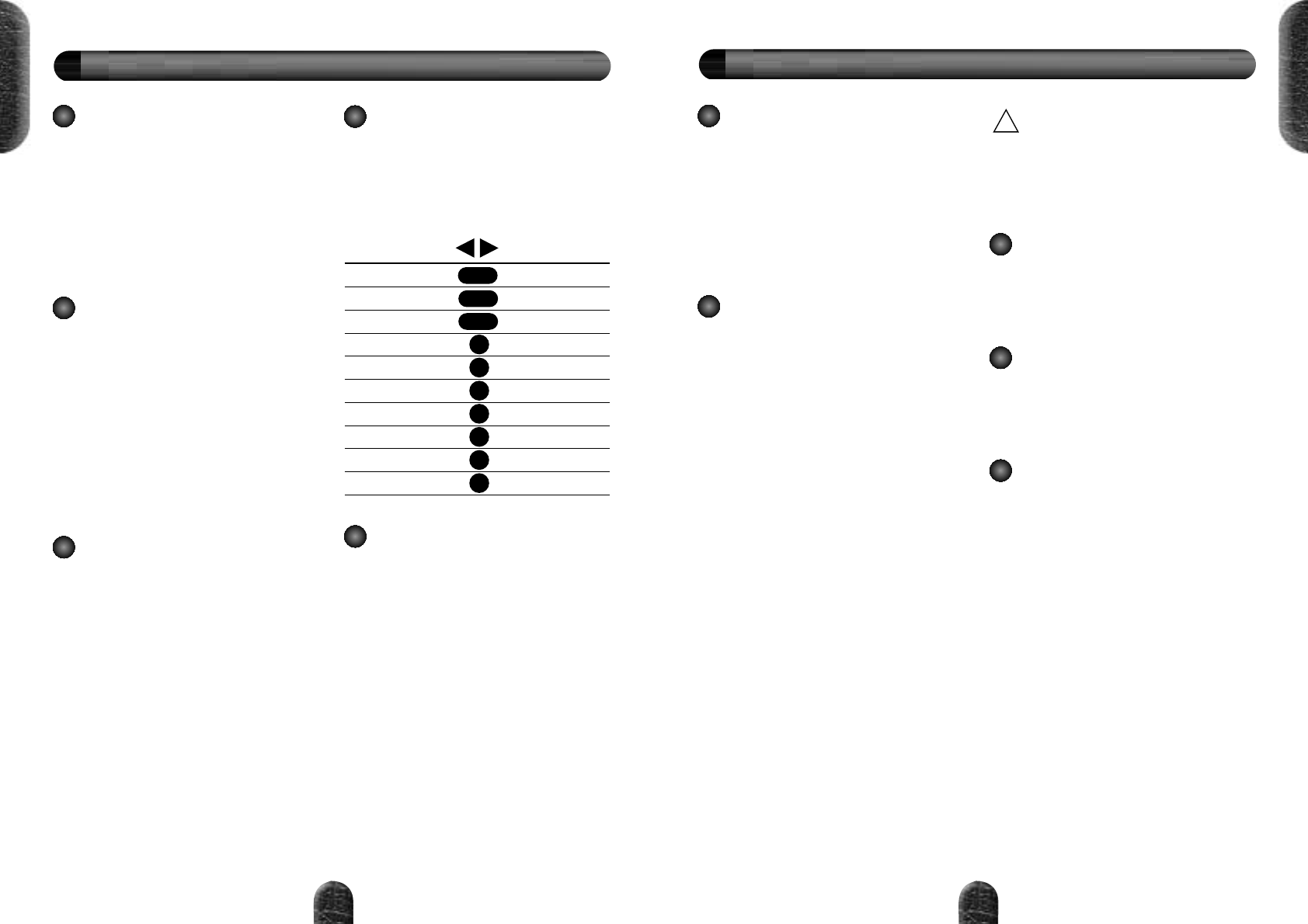
26 Digital FX Program/
Adjust Table
This lists the 16 programs selectable via
the Program control (25) and also indicates
which parameter the Adjust control (24)
modifies for each one. For added convenience,
this table is shown below.
27 Power Switch
Wait for it...yes, this switches the amp on
and off! When the amp is on the power switch
is illuminated and vice-versa. Advanced power
amplifier muting circuitry provides anti-thump
protection on power up and down.
Important Note:
As is the case with an all-
valve amplifier, there will be no signal heard
until the amp's ECC83 preamp valve warms-up
and starts to pass signal. This can take up to
15 seconds so don't panic!
Program
Halls
Rooms
Plates
Gated reverb
Chorus
Flange
Delay
Chorus Room
Ch/Dly/Room
Modulation
Adjust
Decay Time
Decay Time
Decay Time
Decay Time
Rate
Rate
Time
Decay Time
Time
Speed
1 - 3
4 - 6
7 - 9
10
11
12
13
14
15
16
1 Mains Input Connector
Your AVT is provided with a detachable
mains (power) lead which is connected here.
The specific mains input voltage rating that
your amplifier has been built for is shown on
the back panel. Before connecting for the first
time, please ensure that your electricity supply
is compatible with your amplifier. If you have
any doubt, please seek advice from a qualified
technician. Your Marshall dealer will help in
this respect.
2 Loudspeaker Jack Sockets
a) AVT150
There are two speaker jacksockets on the
AVT150. The one marked Internal (8 Ohm) is
where the output of the AVT power amplifier is
connected to its internal 8 Ohm Celestion
loudspeaker.
When an extension speaker is connected
to the other output (marked Extension) the full
power of the 150W power amplifier is
unleashed. Please note that only an extension
cabinet rated at 8 Ohms should be used.
This will provide a parallel load with the
Internal Speaker of 4 Ohms minimum.
b) AVT150H
The AVT150H has two loudspeaker
outputs. The one marked ‘Extension 8Ω’ is for
connection to a single 8 Ohm cabinet. The
output marked ‘Extension 8/4Ω’ can either be
used for connection to a second 8 Ohm
speaker cabinet, or to drive a single 4 Ohm
cabinet.
WARNING:
Always provide the AVT with a load equal
to, or greater than, 4 Ohms.
Note:
Two 8Ω cabinets connected in
parallel = 4Ω
3 Footswitch
For connection of the supplied Stage Foot
Controller (PEDL-00031). This sturdy 6-way
Marshall footswitch allows instant selection of
the 4 channels, plus the two DFX modes. It
also features LEDs to indicate status.
4 Headphones
The headphones output is fully emulated
using an improved version of the circuitry found
on the industry standard JMP-1. Turning the
Master Volume (20) to zero will provide silent
practice.
5 Emulated Line Output
This jack socket carries a specially treated
output signal from your AVT that accurately
emulates the sonic signature of a Marshall
4x12 cabinet. This unerringly accurate
emulation circuitry is Marshall's most advanced
to date and was developed via countless hours
of technical research, playing, listening and
fine-tuning. This output can be used in both
live performance and recording situations to
achieve authentic guitar amp tones, without
having to use a microphone. Turn down the
Master Volume (20) for silent recording.