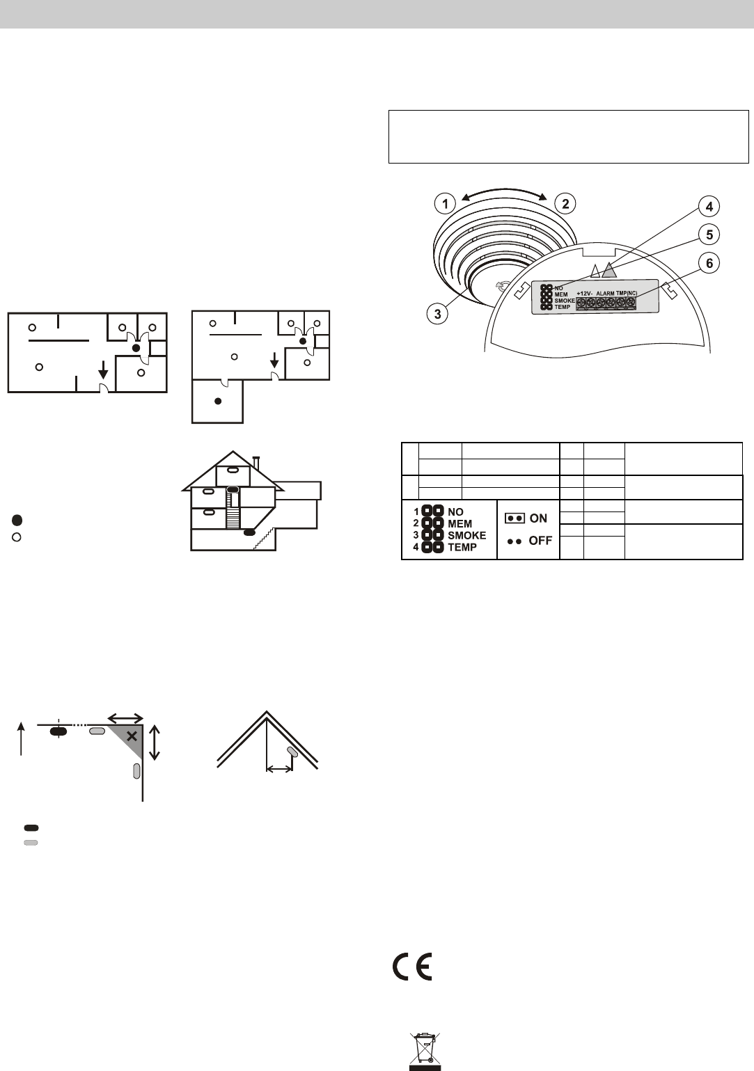
status signalling; 4 – arrow showing where to insert the detector; 5 –
configuration jumpers; 6 – connection terminals;
1. open the detector cover, by turning it anti-clockwise
2. attach the removed plastic base to the desired place with screws (not shown above).
3. set the required detector function – see the table below
ON NO contact 3 OFF
1
OFF NC contact 4 OFF
smoke (EN 54-7) or
heat (EN 54-5)
ON memory ON 3 ON
2
OFF memory OFF 4 OFF
smoke only (EN 54-7)
(not heat)
3 OFF
4 ON
heat only (EN 54-5)
(not smoke)
3 ON
4 ON
Both smoke and heat
(both conditions at the
same time)
4. connect ALARM and TMP terminals – first study the control panel installation manual
before connecting wires to the detector terminal board
TMP- has only NC function
5. connect power supply to the 12V terminals
6. close the module cover. The detector can be inserted in the plastic base in one position
only. The correct position is marked with arrows on both plastic parts.
Fire alarm
Optical detector: When smoke penetrates into the detector, the detector starts
flashing red.
Heat detector: When the temperature reaches the set limits, the detector starts
flashing red.
Alarm memory: If it is enabled, alarm indication continues even when the smoke clears
or when the temperature decreases. The indication is terminated by disconnecting power
supply or by turning the detector anti-clockwise (tamper sensor activation).
Fault indication
The detector checks its functioning. If any faults are discovered, it starts flashing
rapidly for about 2 minutes. Then there are 3 short flashes every 30 seconds.
In such a case, disconnect the power supply for 1 minute and then reconnect it. If the
LED indicator starts flashing again after 1 minute, send the detector to a service centre.
Technical specifications
Power 9 - 15V DC / 5 mA
Smoke detection optical light scattering
Smoke detector sensitivity m = 0.11 - 0.13 dB/m pursuant toEN 54-7
Heat detection class A2 according to EN 54-5
Alarm temperature + 60°C to + 70°C
Operating temperature range -10 to +80°C
Dimensions, weight diameter 126 mm, height 52 mm, 150 g
Conformity EN 54-7, EN 54-5, EN 50130-4, EN 55022
1923-CPD-0244
JABLOTRON ALARMS a.s. hereby declares that the SD-282ST detector is in
compliance with the essential requirements and other relevant provisions of
Directive 1989/106/EC and 2004/108/EC. The original of the conformity
assessment can be found at www.jablotron.com, Technical Support section.
Note: Although this product does not contain any harmful
materials we suggest you return the product to the dealer or
directly to the producer after use. For more information visit
www.jablotron.com.
Need help? Post your question in this forum.
Report abuse
Libble takes abuse of its services very seriously. We're committed to dealing with such abuse according to the laws in your country of residence. When you submit a report, we'll investigate it and take the appropriate action. We'll get back to you only if we require additional details or have more information to share.
Product:
Forumrules
To achieve meaningful questions, we apply the following rules:
First, read the manual;
Check if your question has been asked previously;
Try to ask your question as clearly as possible;
Did you already try to solve the problem? Please mention this;
Is your problem solved by a visitor then let him/her know in this forum;
To give a response to a question or answer, do not use this form but click on the button 'reply to this question';
Your question will be posted here and emailed to our subscribers. Therefore, avoid filling in personal details.
Register
Register getting emails for Jablotron SD-282ST at:
new questions and answers
new manuals
You will receive an email to register for one or both of the options.
Get your user manual by e-mail
Enter your email address to receive the manual of Jablotron SD-282ST in the language / languages: English as an attachment in your email.
The manual is 0,11 mb in size.
You will receive the manual in your email within minutes. If you have not received an email, then probably have entered the wrong email address or your mailbox is too full. In addition, it may be that your ISP may have a maximum size for emails to receive.
The manual is sent by email. Check your email
If you have not received an email with the manual within fifteen minutes, it may be that you have a entered a wrong email address or that your ISP has set a maximum size to receive email that is smaller than the size of the manual.
The email address you have provided is not correct.
Please check the email address and correct it.
Your question is posted on this page
Would you like to receive an email when new answers and questions are posted? Please enter your email address.