The detector is intended to detect human body movement in buildings.
Using two sensors ensures better immunity against triggering by moving
pets.
The signal is processed by a multiple signal analysis method which
guarantees excellent sensitivity and a high resistance to false alarms.
Detection analysis can be adjusted to increase its immunity (if installed in a
problematic location). The detector distinguishes itself with excellent
immunity against high frequency interference and other false signals. It can
be installed on a flat wall or in a corner.
Installation
Installation should only be undertaken by technicians holding a
certificate issued by an authorized distributor. The detector can be installed
on a flat wall or in the corner of a room. The expected installation height is
120 cm above the floor. Objects rapidly changing temperature, (electrical
heaters, gas appliances etc) should not be positioned within the detection
field. Moving objects with a temperature close to that of a human body
(such as curtains moving above a radiator) should also be avoided. The
detector should not face windows or spotlights or be installed in places with
obvious air flow (e.g. near ventilation fans, air holes or badly sealed doors
etc.).
There should be no obstacles blocking the detection field and the
detector should be kept away from metal objects (they could interfere with
radio communication).
1. Open the detector cover (by pressing the tab) – do not touch the
PIR sensors inside
2. Remove the PCB – it is held by two internal tabs
3. Make the necessary holes for cables in the rear plastic cover and
punch screw holes (at least one screw should go through the
tamper-sensitive section)
4. Screw the rear cover to the wall approximately 120 cm above the
floor (vertically, with the tab down)
5. Return the PCB into the rear housing and connect the cable wires
to the terminals
6. Close the cover
Warning: avoid dirtying or damaging the PIR sensor inside the detector
(by touching, greasing or scratching).
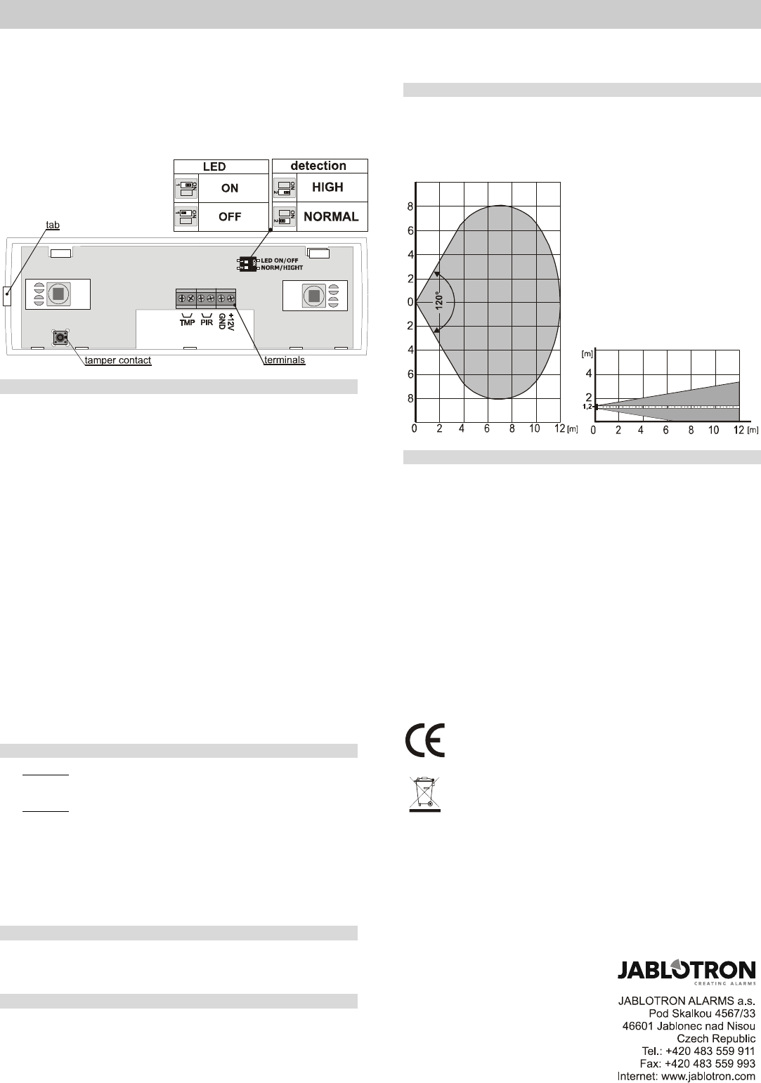
DIP switches
Switch 1: LED ON / OFF in the LED ON position, each movement is
signalled by the flash of a red LED, an alarm is signalled by a 2-second flash.
The signalling is blocked in the OFF position.
Switch 2: NORM / HIGH defines the immunity to false alarms.
The NORM position combines very good immunity with fast sensor
reactions. The detector is activated if it detects movement in one zone and then
in the second zone within 3 seconds.
The HIGH position increases sensor immunity at the expense of speed (it is
used with problematic installations). The detector is activated if there are two
NORM activations in 10 seconds.
Warning: The most frequent cause of false alarms is wrong detector
positioning.
Terminals
+12V, GND power supply
PIR, PIRPIR alarm output – normally closed
TMP, TMPTAMPER output – normally closed
Detector testing
After switching on the power, wait for 1 minute for the detector to
stabilize. If LED ON is activated, stabilization is signalled by a
continuously lit red LED.
Each detected movement is indicated by the detector’s LED (LED
switch in the detector must be in LED ON position during testing)
Move in the covered area to test the detector coverage.
Opening the detector cover causes the TMP terminals to open-circuit
Detection characteristics
The detector has two detection zones each of which covers an angle of
120° and a distance of 12m. The imaginary dividing line between both
zones is determined by the detector installation height. The recommended
installation height is about 120cm.
Top view
Side view
Technical parameters
Power supply: 12 V DC ± 25%
Power consumption (LED off): max. 3 mA
Maximum consumption (LED on): max. 7 mA
Terminal size: 1 mm
2
Recommended installation height 1.2 m above the floor
Detection angle / detection range 120° / 12 m (with basic lens)
Initialisation: max. 60 s
PIR output impulse length: 2 s
Alarm output: normally closed 60V / 100mA
internal resistance max.30 Ohm
Tamper output: normally closed 60 V / 100mA
internal resistance max.30 Ohm
Operational environment according to EN 50131-1 II. Indoor general
Operational temperature range -10 to +40 °C
Dimensions 180 x 60 x 55 mm
EN 50131-1,CLC/TS 50131-2-2, EN 50131-5-3
classification grade 2 (medium risk)
Also complies with ETSI EN 300220, EN 50130-4, EN 55022, EN 60950-1
JABLOTRON ALARMS a.s. hereby declares that the detector is
in compliance with the essential requirements and other relevant
provisions of Directive 2004/108/EC The original of the conformity
assessment can be found at www.jablotron.com, Technical Support
section.
Note: Although this product does not contain any harmful
materials we suggest you return the product to the dealer or directly
to the producer after use. More detailed information is available at
www.jablotron.com
Need help? Post your question in this forum.
Report abuse
Libble takes abuse of its services very seriously. We're committed to dealing with such abuse according to the laws in your country of residence. When you submit a report, we'll investigate it and take the appropriate action. We'll get back to you only if we require additional details or have more information to share.
Product:
Forumrules
To achieve meaningful questions, we apply the following rules:
First, read the manual;
Check if your question has been asked previously;
Try to ask your question as clearly as possible;
Did you already try to solve the problem? Please mention this;
Is your problem solved by a visitor then let him/her know in this forum;
To give a response to a question or answer, do not use this form but click on the button 'reply to this question';
Your question will be posted here and emailed to our subscribers. Therefore, avoid filling in personal details.
Register
Register getting emails for Jablotron JS-22 at:
new questions and answers
new manuals
You will receive an email to register for one or both of the options.
Get your user manual by e-mail
Enter your email address to receive the manual of Jablotron JS-22 in the language / languages: English as an attachment in your email.
The manual is 0,08 mb in size.
You will receive the manual in your email within minutes. If you have not received an email, then probably have entered the wrong email address or your mailbox is too full. In addition, it may be that your ISP may have a maximum size for emails to receive.
The manual is sent by email. Check your email
If you have not received an email with the manual within fifteen minutes, it may be that you have a entered a wrong email address or that your ISP has set a maximum size to receive email that is smaller than the size of the manual.
The email address you have provided is not correct.
Please check the email address and correct it.
Your question is posted on this page
Would you like to receive an email when new answers and questions are posted? Please enter your email address.