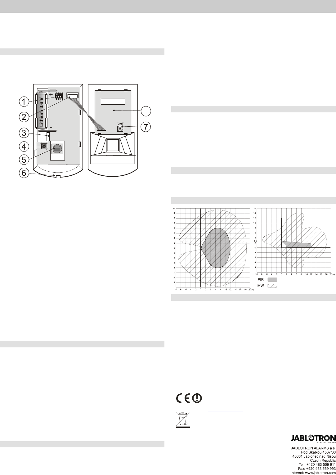
PIR sensor; 6. front cover tab; 7. MW sensitivity setting; 8. MW detector
1. Open the detector cover by pressing the tab (6) and remove the PCB
which is held by an internal tab (3) Avoid touching the internal PIR
element or damaging the antenna.
2. Punch screw holes through the rear plastic cover according to the
installation point, either for a corner or for a flat wall At least one screw
should penetrate the tamper-sensitive section.
3. Screw the rear cover to the wall, about 2.5 meters above the floor
(vertically, with the tab down).
4. Return the PCB to its original place till the tab (3) clicks..
5. Leave the battery disconnected and the cover open and then follow the
control panel or receiver manual. The basics of enrollment are:
• Enter enrollment mode on the control panel by keying in “1” in
Service mode.
• Install a battery into the detector to activate enrollment.
• Exit enrollment mode by pressing “#”
6. Close the detector cover till the tab clicks. The supplied screw can secure
the tab.
7. After installing a battery into the detector, allow three minutes for
stabilization. During this period the LED is continuously lit.
Notes:
To enroll a detector after having already connected a battery, first disconnect
the battery, and press and release the tamper switch to discharge any
remaining charge to get the device ready for enrollment.
The detector can also be enrolled by entering the serial number – the last
eights numbers of the barcode, which is placed inside the detector.
To follow the EN 50131-2-4 the tab must be secured by the supplied screw.
DIP switch Setting
Switch no.1: DEL / INS: OFF (DEL) provides entrance & exit delays for
detectors installed in a building entrance route. The ON (INS) allows the
detector to instantly trigger alarm activation if the control panel is armed.
DIP switch no.1 only has an effect if the detector has a natural reaction
assigned to it in the OASiS control panel. It also has no effect when used with
a UC-8x or AC-8x receiver.
Switch no.2: PIR NORM / HIGH: selection of immunity to false alarms.
The OFF (NORM) position combines very good immunity with fast sensor
reactions. The ON (HIGH) position gives increased immunity with a slower
reaction time and is only used for problematic installations.
Switch no.3: MW NORM / HIGH sets the time period after PIR detection in
which the MW detection is active. The position OFF – 1 s, ON – 2 s
Switch no.4: MW NORM / TEST. The position OFF is for the standard function
of the detector. The MW detection is triggered by the PIR detection part for one or
two seconds according to switch no.3. The position ON - MW detection works
continuously for testing purposes (walk test).
Testing the detector
15 minutes after closing the detector cover, the LED indicators show detector
activation. A short flash of the red light indicates PIR detection and a long flash
(2 sec) indicates MW confirmation of the movement.
For the proper functioning of the detector, it is essential to set the MW
detection field according to the place which should be monitored. For setting
up, switch the fourth DIP switch to the TEST position. Sensitivity (monitoring
range) can be adjusted by a potentiometer on the MW detection part located
inside the front cover of the detector. Turning clockwise increases the
sensitivity (range). Avoid selecting too high a sensitivity as the detection can
cover e.g. nearby rooms. Generally the MW detection field should be the same
as the PIR detection one. After setting up, switch the DIP switch back to
NORM position.
To save battery energy, the PIR detector switches to battery-save mode 15
minutes after the cover is closed. During battery-save mode the PIR sensor still
always watches out for movement. The first movement detected and consecutively
confirmed by the MW part is then signaled to the control panel instantly, and for the
next 5 minutes the PIR sensor ignores any further movement. After these 5
minutes, the PIR sensor then returns to watching out for movement until re-
triggered.
Battery replacement
The detector regularly checks its battery conditions. If battery voltage is
too low, then the report is sent to the control panel to inform the user or
installer. The detector continues to work and each detected movement is
confirmed by a brief LED flash. The battery should be replaced within two
weeks by a qualified technician in SERVICE mode.
After battery replacement, test the functioning of the detector. Expired
batteries should not be thrown into the garbage, but disposed of according
to local regulations.
Removing the detector from the system
If a detector is removed, the control panel reports the removal. The detector
has to be deleted from its address in the control panel before intentional
removal.
Detection characteristics
Technical parameters
Power supply: Lithium battery type LS(T)14500 (3.6V / 2,4 Ah AA)
Typical battery lifetime: approx. 2 years (DIP switch 3: NORM)
Communication band: 868 MHz, Oasis Protocol
Communication range: approx. 300m (open area)
Recommended installation height: 2.0 to 2.5 m above floor level
PIR detection angle/detection range: 110° / 12 m (with basic lens)
MW detection range / frequency 0.5 to 20 m / 9.35 GHz
Operational environment according to EN 50131-1 II. indoor general
Operational temperature range -10 to +40 °C
EN 50131-1, EN 50131-2-4, EN 50131-5-3 classification: grade 2
Dimensions, weight 110 x 60 x 55 mm, 140 g
Complies with ETSI EN 300220, ETSI EN 300 440-1, EN 50130-4, EN 55022, EN 60950-1
Can be operated according to ERC REC 70-03
Operation requires notification national telecommunication offices of Finland, France, Italy,
Serbia and Montenegro, Spain, Sweden, UK
JABLOTRON ALARMS a.s. hereby declares that the
JA-80W is in compliance with the essential requirements
and other relevant provisions of Directive 99/5/EC. The
original of the conformity assessment can be found at
www.jablotron.com, Technical Support section
Note: Although this product does not contain any harmful
materials we suggest you return the product to the dealer or
directly to the producer after use.
Need help? Post your question in this forum.
Report abuse
Libble takes abuse of its services very seriously. We're committed to dealing with such abuse according to the laws in your country of residence. When you submit a report, we'll investigate it and take the appropriate action. We'll get back to you only if we require additional details or have more information to share.
Product:
Forumrules
To achieve meaningful questions, we apply the following rules:
First, read the manual;
Check if your question has been asked previously;
Try to ask your question as clearly as possible;
Did you already try to solve the problem? Please mention this;
Is your problem solved by a visitor then let him/her know in this forum;
To give a response to a question or answer, do not use this form but click on the button 'reply to this question';
Your question will be posted here and emailed to our subscribers. Therefore, avoid filling in personal details.
Register
Register getting emails for Jablotron JA-80W at:
new questions and answers
new manuals
You will receive an email to register for one or both of the options.
Get your user manual by e-mail
Enter your email address to receive the manual of Jablotron JA-80W in the language / languages: English as an attachment in your email.
The manual is 0,11 mb in size.
You will receive the manual in your email within minutes. If you have not received an email, then probably have entered the wrong email address or your mailbox is too full. In addition, it may be that your ISP may have a maximum size for emails to receive.
The manual is sent by email. Check your email
If you have not received an email with the manual within fifteen minutes, it may be that you have a entered a wrong email address or that your ISP has set a maximum size to receive email that is smaller than the size of the manual.
The email address you have provided is not correct.
Please check the email address and correct it.
Your question is posted on this page
Would you like to receive an email when new answers and questions are posted? Please enter your email address.