The JA-80F is a component of Jablotron’s OASiS alarm system and is
designed to control and program the system. It has a built-in proximity access
card reader and allows the wiring up of a separate door detector. The battery-
powered keypad communicates wirelessly using OASiS protocol.
Installation
Installation shall only be undertaken by technicians holding a certificate
issued by an authorized distributor. The keypad is for indoor installation
only, typically by the main entrance door. Avoid locating it close to metal
objects which could shield radio communication.
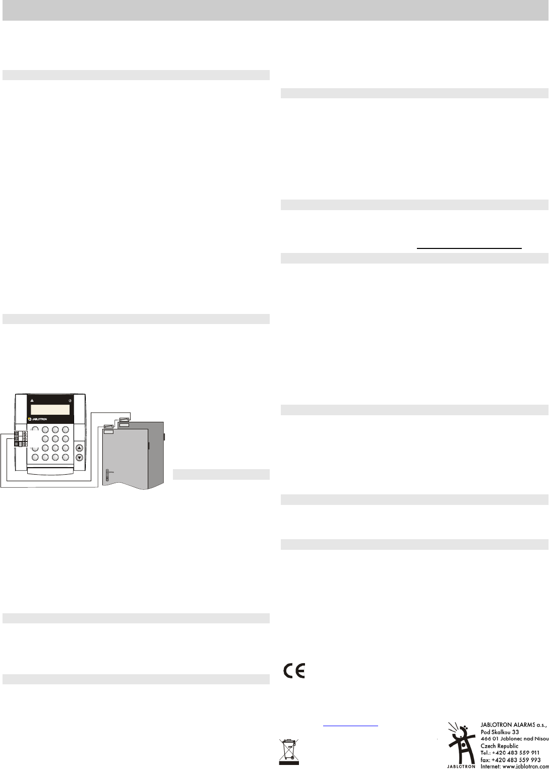
1. Open the keypad housing (by pressing the tab on the bottom) and
disconnect the inter-housing connection cable inside (by pulling the
connector from the board)
2. Install the rear housing to the desired location
3. Install the external hard-wired detector (if required)and route its
cable through the rear housing
4. Enroll the keypad to the control panel (see the control panel
installation manual) as follows:
• Enter enrollment mode in the control panel (if the system does
not have a keypad already, briefly short the reset link on the
control panel main board, or if a keypad is present, then press
key 1 in service mode).
• Install the battery into the keypad to trigger enrollment.
• Exit enrollment mode by pressing the # key.
5. Connect the inter-housing cable to the board. If a door detector
and an external AC adaptor are used, then connect their cables too.
Attach the keypad to the rear housing.
6. Instructions on how to use the keypad can be found in the control
panel operating manual.
Installing a door detector
It is possible to wire up a detector(s) to the keypad. The IN input terminal is
triggered when disconnected from GND. The control panel’s natural reaction
to the IN input being triggered is a delayed intruder alarm linked to the
keypad‘s address. If desired, another reaction can be programmed in the
control panel. The IN input can indicate a door being permanently open
(status reaction). If the IN input is never used then it must be shorted to GND.
Note: The lifetime of
the battery is reduced
proportionally to how
frequently the door
detector is triggered
and how often and how
long the keypad is
battery-powered.
Keypad sleep mode
When battery-powered, the
keypad saves energy by
turning itself off when the cover is closed or automatically after 20 seconds of
inactivity (15 minutes in service mode). The keypad is woken up by: opening
the keypad‘s flip cover, pressing any key, or triggering the wired door detector.
Recommendation:install the keypad with the door detector wired to its
IN terminal. The door detector will always turn the keypad on when the door
is opened and the keypad can also indicate the entrance delay and be ready
to read access cards. You will also save money on a wireless door detector.
Note: If the keypad unit is powered by an AC adaptor there is no sleep mode,
but 3 minutes after setting the system, status indication stops. If desired, the
system setting/unsetting status can be programmed in the control panel to be
permanently indicate by the keypad.
Optional AC adapter
If the keypad is powered by an AC adapter (model: Jablotron DE01-12 for
terminals: +U and GND), it will not turn off after 20 seconds of inactivity. If
the adapter is used, batteries should still be installed. Only turn on the AC
adapter after the keypad unit has been powered up by batteries and the
two halves of the housing are back together.
Keypad menu – language selection and door bell function
If the ∗ key is kept pressed during battery connection the internal keypad
menu will be displayed allowing the selection of the desired language. Using
the arrows choose your language and confirm selection by the ∗ key.
In this menu the door bell function can also be enabled or disabled (if
enabled the keypad makes a sound when its IN input is triggered).
Notes:
• The menu can be displayed even if the keypad has not been enrolled to
the control panel.
• If you wish to display the menu on a keypad which already has its
battery installed, disconnect and reconnect the batteries first.
• Each keypad has its own menu, i.e. each keypad in the system can
have its own unique settings.
• The keypad keeps its settings even if its power is disconnected (settings
can only be altered via the keypad menu).
Testing keypad communication
In service mode, the control panel allows the keypad’s radio signal to be
checked, including signal strength measurement. To test the keypad
signal, trigger either its IN input or its tamper sensor.
Note: the control panel measures the strength of the signal transmitted
by the keypad. It is impossible to measure the signal strength received by
the keypad from the control panel. If the keypad has lost communication
with the control panel (e.g. if the control panel is damaged) it would
display a communication error. If you re-power a control panel which
previously worked with a keypad, and the keypad does not function, then
we recommend disconnecting and re-connecting the keypad batteries.
Disabling the tamper sensor
To disable the tamper sensor, short out the jumper in the keypad unit
close to the tamper sensor (equipped with a spring). This is useful when
carrying the keypad unit around while servicing the system. During
normal use of the system this jumper must remain open circuited
.
Keypad text editing
There are two kinds of text: device and code names (displayed on the
second line after the address number) and other system text.
The names can be edited via the keypad after pressing and holding the
? key in service mode – see the control panel installation manual. The
edited text is only stored in the keypad unit used for editing.
The most convenient way to edit text is to use a PC running OLink
software. To transfer edited text from a PC to the keypad, the keypad
(with its batteries installed) has to be connected to the OASiS system‘s
digital bus (i.e. one cable from the keypad to the control panel, and
another cable from the control panel to the PC). If there are multiple
keypads, they can all be connected together (via the digital bus) while
transferring edited text from the PC, or you can transfer text to each
keypad, one at a time. We recommend using a digital bus splitter (model
BS-84). OLink software also allows editing of the keypad’s system text.
Battery replacement
The system checks the battery status and if discharged it will inform the
end user or the installer. The keypad will continue to work but will also
indicate a low battery. Batteries should be replaced within 2 weeks by a
qualified technician in service mode.
Note: It is strongly recommended to change both batteries together
and with identical types (manufacturer).
Do not put expired batteries in the garbage, but follow local regulations..
Removing the keypad from the system
If the keypad is removed from the system, the control panel indicates this
event. If you want to uninstall the keypad, it must also be erased in the
control panel.
Technical specifications
Power supply 2x lithium batteries type CR123A (3.0V)
Typical battery lifetime approx. 3 years (with a max.of 2 daily activations)
Communication frequency 868 MHz, OASiS protocol
Communication range approx. 100m (open area)
RFID cards Jablotron PC-01 or PC-02 (EM UNIQUE 125kHz)
Door detector input IN = normally closed loop
Dimensions 113 x 121 x 63 mm
Environment according to EN 50131-1 II. internal
Operating temperature range -10 to +40 °C
EN 50131-1, CLC/TS 50131-3, EN 50131-5-3 classification class 2
Can be operated according to ERC REC 70-03
FCC ID VL6JA80F
Jablotron Ltd. hereby declares that the JA-80Fis in compliance with the
essential requirements and other relevant provisions of Directive 1999/5/EC
and complies with part 15 of the FCC rules. Operation is subject to the following
two conditions: 1. This device may not cause harmful interference, and 2. This device must
accept any interference received, including interference that may cause undesired
operation.
CAUTION: Changes or modifications no expressly approved by Jablotron could void the
user´s authority to operate the equipment.The original of the conformity assessment can
be found at www.jablotron.com
, Technical Support
section.
Note: Although this product does not
contain any harmful materials we suggest
you return the product to the dealer or
directly to the producer after use.
In
te
rn
et
: www.
jab
l
ot
r
o
n.
c
z
Tel.: +420 483559 999
fax: +420 483559 993
P
od
S
k
a
lk
ou
33
4
66
0
1
Jab
l
o
n
ec
n
ad
Ni
so
Czech Republic
OASIS 80
A B C
ABC
?
B
A
IN
GND
+U
Need help? Post your question in this forum.
Report abuse
Libble takes abuse of its services very seriously. We're committed to dealing with such abuse according to the laws in your country of residence. When you submit a report, we'll investigate it and take the appropriate action. We'll get back to you only if we require additional details or have more information to share.
Product:
Forumrules
To achieve meaningful questions, we apply the following rules:
First, read the manual;
Check if your question has been asked previously;
Try to ask your question as clearly as possible;
Did you already try to solve the problem? Please mention this;
Is your problem solved by a visitor then let him/her know in this forum;
To give a response to a question or answer, do not use this form but click on the button 'reply to this question';
Your question will be posted here and emailed to our subscribers. Therefore, avoid filling in personal details.
Register
Register getting emails for Jablotron JA-80F at:
new questions and answers
new manuals
You will receive an email to register for one or both of the options.
Get your user manual by e-mail
Enter your email address to receive the manual of Jablotron JA-80F in the language / languages: English as an attachment in your email.
The manual is 0,13 mb in size.
You will receive the manual in your email within minutes. If you have not received an email, then probably have entered the wrong email address or your mailbox is too full. In addition, it may be that your ISP may have a maximum size for emails to receive.
The manual is sent by email. Check your email
If you have not received an email with the manual within fifteen minutes, it may be that you have a entered a wrong email address or that your ISP has set a maximum size to receive email that is smaller than the size of the manual.
The email address you have provided is not correct.
Please check the email address and correct it.
Your question is posted on this page
Would you like to receive an email when new answers and questions are posted? Please enter your email address.