The JA-63S-80 wireless optical smoke and heat detector for Oasis system
This device is designed to detect the presence of fire inside residential or commercial
buildings. It should not be installed in industrial premises. The battery-powered detector
has a built-in local warning siren combined with a transparent LED indicator. The alarm
information can also be transferred via a wireless connection to the JA-80 OASIS
system.
The JA-63S–80 detector combines an optical smoke sensor with a heat sensor. Both
sensors have their outgoing signals processed digitally, resulting in higher false alarm
immunity. The optical sensor works using a light diffusion principle and is very sensitive to
the presence of large-sized particles which are characteristic of dense smokes. By
contrast, the sensor is less sensitive to small-sized particles which are typical of cleanly
burning fires. In particular, the smoke sensor is not capable of detecting the by-products of
cleanly-burning fluids such as alcohols, for instance. This deficiency is compensated for
by the built-in heat sensor. This sensor provides a slower reaction when compared to the
smoke sensor, but is much better at reacting to fires with rapidly rising heat producing only
a little smoke.
Smoke/heat sensor participation is configurable by DIP switches.
Detectionrange, detector positioning
Exposing fire conditions to the smoke and heat sensors requires some level of air
circulation. It is therefore necessary to install the JA-63S–80 detectors in such a place on
the ceiling that (in the case of fire) smoke masses are forced to go in the direction of the
detector’s position. This can usually be achieved in most buildings. However, the
JA-63S–80 is not suitable for installation in outdoor spaces or interiors with an extremely
high ceiling where fire by-products would not reach the detector position.
The following table shows the detector’s working range in relation to the height of the
ceiling on which the detector is installed. The range is expressed as the radius of the
circular fire detection area for a detector installed on a ceiling directly above:
Ceiling height (m)
< 4,5
4,5÷6
6÷8
8÷11
11÷25
> 25
Smoke
detection
7,5* m 7,5* m 7,5* m 7,5* m
Not
suitable
Not applicable
Heat
detection
5* m 5* m 5* m Not suitable
Not
applicable
Not applicable
Not applicable – meant for a particular ceiling height range
Not suitable –not usually used in such cases
* – the radius of the detection area below the detector
•
Installation on a horizontal level ceiling
Due to the possible occurrence of a cold air layer right under the ceiling, the detectors
must not be imbedded into the ceiling. The distance between any point to be
protected and an imaginary vertical line fromthe nearest JA-63S–80 detector down to the
floor must not exceed the radius indicated in the table.
•
Installation on a sloping ceiling
If the JA-63S–80 is installed just under an apex formed by the joining of two sloping
ceilings the values indicated inthe table can be increased by 1% for every degree of
slope up to a maximum of 25%. If the space to be protected is under a saw-tooth type
of roof, JA-63S–80 detectors should be installed under each apex. However, a roof with
a shallow saw-tooth form can be acceptable if the height difference between the highest
and lowest parts of the ceiling does not exceed 5% of the total ceiling height.
•
Walls, partitions, obstacles, and trussed ceilings
The JA-63S-80 must not be installed closer than 0.5 m from any wall or partition.
A narrow room with a width of less than 1.2m requires the detector(s) to be placed at a
distance of at least one third of the room’s width away. In the case of separating walls
(partitions, warehouse objects) which do not reach the ceiling, the space is considered to
be fully separated if the gap between the top of the separating wall and the ceiling
does not exceed 0.3 mA free space of at least 0.5m is required under the detector.
Irregularities in ceiling shape which do not exceed 5% ofceiling height are considered
insignificant – the ceiling can be regarded as being even and limits from the table are
applicable. However, any irregularity (including beams) exceeding 5% of the ceiling
height is considered to be a wall with the consequences stated above.
•
Ventilation and air circulation
The detectors must not be installed directly by a fresh air inlet, e.g. air conditioning
vents. In the case of air being supplied through a perforated ceiling, each detector must
be placed so that no perforation hole occurs within 0.6m of the detector.
•
Avoid installing the detector in the following locations:
•Places with poor air circulation (niches, corners, apexes of A-shaped roofs).
•Places exposed to dust, cigarette smoke or steam.
•Places with over-intense air circulation (close to ventilators, heat sources or air
conditioning outlets).
•Kitchens and other cooking places (because steam, smoke or oily fumes can reduce
detector sensitivity).
Caution: The most common reason for the detector to be accidentally
triggered is improper detector location.
See CEN/TS 54-14 standards for detailed installation guidelines
.
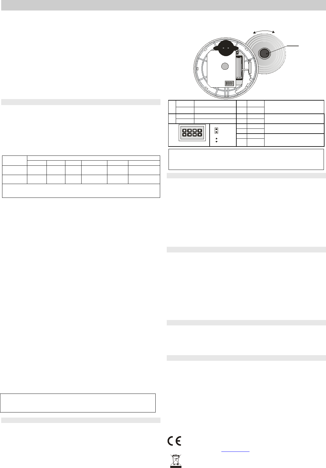
Installation
1.Open the detector by turning the rear cover to the left and remove the battery
2.Screw the rear coveronto the desired location
3.Set the required functionvia the jumpers– see the table below
4.Please read the receiving device (control panel) installation manual before you
connect the battery (remove the insulation tape) and set the control panel in learning
mode
5.When the battery is connected, the detector sends a signal to connect into the
system
6.After installing the detector, allow approx. 20 seconds for stabilisation. This period is
indicated by the LED being continuously lit and is followed by an auto-test.
Successful performance of the auto-test is confirmed acoustically.
O
p
e
n
C
l
o
s
e
TEST
+
1.
5 V
A
A
1
1
ON INSTANT alarm mode3 OFF
Smoke (EN 14064) or heat (EN
54-5)
OFF
FIRE alarm mode
4 OFF
2
ON
Memory ON
3
ON
Only smoke (EN 14604) (heat
indifferent)
OFF
Memory OFF
4
OFF
1
1234
ON
OFF
3
OFF
Only heat (EN 54-5) (smoke
indifferent)
4
ON
3
ON
Smoke and heat (both
simultaneously)
4 ON
Closing the detector is disabled if no battery has been installed!
Testing the detector is automatically performed up to 10 secs after
battery insertion. New settings are saved directly afterwards.
Fire alarm
Optical smoke sensor: Smoke entry into the detector is indicated as a pre-alarm state
by the LED flashing. If the smoke threshold density is exceeded, a siren sound is
generated, gradually increasing in volume.
Heat sensor:indication logic is equal to that of the smoke sensor.
Alarm memory: It is switched ON/OFF via DIP 2 as shown in the table. If the event
memory is armed at the time of alarm, alarm LED indication continues even if normal
conditions are restored. The indication can be stopped by pressing the button.
Silencing the siren during an alarm: During a fire alarm, the detector LED flashes 2
times briefly and the built-in siren sounds (ata higher intensity than during a test). Under
these conditions the siren can be silenced by pressing the test button for approx. 3sec.
However, if normal conditions are not restored within approx. 10 minutes (the smoke
does not clear from the room or the temperature does not drop), the siren re-activates.
Testing the detector
Testing the detector is automatically performed up to 10 secs after battery
insertionor after changing the settings on the jumpers.The functioning of the detector
can be tested by pressing and holding the test button for approx. 3 seconds. A properly
functioning detector responds with one beep and a short flash. The alarm information is
transferred to the system. A fault is indicated by 4 beeps and the LED permanently
flashing. Inthis case, remove the battery and re-insert it after 1 minute. If the fault
indication occurs again (the LED starts permanently flashing after about 1 minute), consult
the installer company.
The detector should be tested this way at least once in every 30days.
Warning: Never start a fire in a building to test the detector.Instead, use smoke-
simulating aerosols for realistic testing. The information for the control panel is seen as a
FIRE zone.
Battery replacement
The detector monitors its battery voltageand if too low, a report is sent to the control
panel and a short acoustic warning signal is emitted every 45 seconds. Battery
replacement should not be delayed by more than two weeks. As mentioned above, the
detector is automatically tested after each battery insertion. Expired batteries should
not be thrown into the garbage, but disposed according to local regulations.
Specification
Voltage1x AA 1.5 V alkaline battery
Battery lifetimetypically 2 years
Communication frequency868,5MHz, OASiS protocol
Wireless communication range 100m (in open space)
Smoke detection optical, light dispersion
Smoke sensor sensitivity m = 0.11 - 0.13 dB/m pursuant to EN 14 604
Temperature detectionclass A2 pursuant to EN 54-5
Fire-alarm temperature+60 °C to +70 °C
Acoustic power of the built-in siren min. 85 dB/3m A
Operational temperature range-10 to +70 °C
Dimensionsdiameter 126 mm, height 65 mm
Complies with EN 14 604, A2 EN 54-5, EN 50130-4,
EN 55022, ETSI EN 300220, EN 60950-1
Terms of useERC REC 70-03
1293-CPD-0261
JABLOTRON ALARMS a.s. hereby declares that the JA-63S–80 is in
compliance with the essential requirements and other relevant
provisions of Directive 1989/106/EC and 1999/5/EC. The original of the
conformity assessment can be found on the web site
www.jablotron.com, Technical Support section.
Note: Dispose of batteries safely depending on battery type and local regulations.
Although this product does not contain any harmful materials we suggest you return the
product to the dealer or directly to the manufacturer after use.
The JA-63S-80 wireless optical smoke and heat detector for Oasis system2 / 2 MKY53100
Need help? Post your question in this forum.
Report abuse
Libble takes abuse of its services very seriously. We're committed to dealing with such abuse according to the laws in your country of residence. When you submit a report, we'll investigate it and take the appropriate action. We'll get back to you only if we require additional details or have more information to share.
Product:
Forumrules
To achieve meaningful questions, we apply the following rules:
First, read the manual;
Check if your question has been asked previously;
Try to ask your question as clearly as possible;
Did you already try to solve the problem? Please mention this;
Is your problem solved by a visitor then let him/her know in this forum;
To give a response to a question or answer, do not use this form but click on the button 'reply to this question';
Your question will be posted here and emailed to our subscribers. Therefore, avoid filling in personal details.
Register
Register getting emails for Jablotron JA-63S-80 at:
new questions and answers
new manuals
You will receive an email to register for one or both of the options.
Get your user manual by e-mail
Enter your email address to receive the manual of Jablotron JA-63S-80 in the language / languages: English as an attachment in your email.
The manual is 0,07 mb in size.
You will receive the manual in your email within minutes. If you have not received an email, then probably have entered the wrong email address or your mailbox is too full. In addition, it may be that your ISP may have a maximum size for emails to receive.
The manual is sent by email. Check your email
If you have not received an email with the manual within fifteen minutes, it may be that you have a entered a wrong email address or that your ISP has set a maximum size to receive email that is smaller than the size of the manual.
The email address you have provided is not correct.
Please check the email address and correct it.
Your question is posted on this page
Would you like to receive an email when new answers and questions are posted? Please enter your email address.