INSTRUCTION MANUAL ROOM CLIMATE CONTROL DEVICEGS10.00PRO
SAFETY INSTRUCTIONS AND BASICS
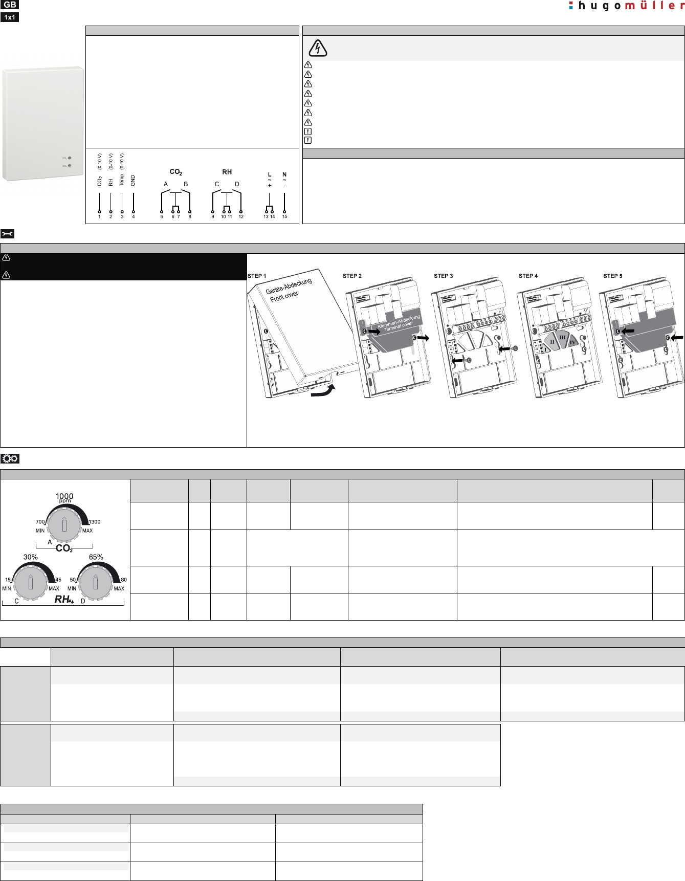
Technical data / Connection diagram
Safety instructions
Power supply:
Connect as stated on the product!
CAUTION!DANGER OF LIFE / RISK OF FIRE AND ELECTRIC SHOCK!
!!!Installation and assembly of electrical equipment must be carried out only by a skilled person!!!
!!!For devices with 24V ACDC
supply voltage following applies:
SELV
Channels (potential-free):
4 switching channels, normally open
Connect the supply voltage/frequency as stated on the product!
Disconnect device from power supply for wiring and installation purposes! Check power supply is disconnected!
After completing the installation the terminal cover MUST be reattached! The device may only be operated with front and terminal cover!
The safety precautions of DIN VDE 0100, electric shock, and fire danger have to be met.
Defective devices / sensors have to be put out of service immediately!
For devices with 24V ACDC supply voltage following applies: The supply voltage must meet the requirements for SELV!
Installation and assembly of electrical equipment must be in accordance with local building and electrical codes!
Warranty void if housing opened by unauthorised person!
Donotuse the sensor for safety-relevant gas measurements!
Switching capacity:
Connect as stated on the product!
Analogue control outputs:
3 x 0-10 Volt
Permitted ambient temperature:
0°…+50°C
Housing:
self-extinguishing thermoplastic
Mounting:
wall mounting
Type of connection:
Screw terminals
Type of protection:
IP 20 to DIN EN 60529
Class of protection:
II when installed according to regulations
Features of actions:
1B
Usage / disposal
The climate control deviceis provided for use in interior andliving areas!
The device includes sensors for measuring and controlling CO
2
concentration, relative humidity and temperature.
The relay switches in according to the set threshold values for CO
2
and relative humidity (example for application: ventilation). Via
analogue control outputs the measured values of the CO
2
concentration, relative humidity and temperature can be output.
The device is to be disposed in an environment-friendly way and according to current law.
ASSEMBLY
Assembly
Disconnect device from power supply for wiring and installation
purposes! Check power supply is disconnected!
Attention! You have to check and consider the safety instructions above!
This deviceis suitablefor wall mounting or for mounting on a flush-mounting box.
The device should not be exposed to air draught or direct sunlight.
Don´t install it curtains, or in niches, or close to heat sources.
The device should not be exposed todusty environment.
Ensure that no dust get inside of this device.
For devices with 24V ACDC supply voltage following applies:
The supply voltage must meet the requirements for SELV!
Afterinitial startup, thedevicerequiresup to 5 minutesuntil the firstcorrect
measurementis possible
Installation note: For an easy mounting and installationyou can unplugthe ribbon cableto remove the front covercompletely. (Ribbon cable: logic cable connection
between front-cover and back-cover). After mounting / installation=>For a proper function of the device youhave to reconnectin the ribbon cable.
STEP 1:Open the deviceat the bottom and remove the front cover!
STEP 2:Remove the terminal cover (shown in grey)!
STEP 3:Mountthe rear cover to the wall or on a flush-mounting box(consider STEP 4)!
STEP 4:Feed the cables through the appropriate cable passages:
Cable passage I:Cables for analogue outputs and GND (Terminal 1,2,3,4)
Cable passageII:Cables for Relay A and Relay B (Terminal 5,6 / 7,8)
Cable passageIII: Cables for Relay C and Relay d (Terminal 9,10 / 11,12)
Cable passageIV:Cablesof the supply voltage (Terminal 13,14,15)
STEP 5:After completing the installation the terminal cover MUST be reattached!
STEP 6:Reattach the front cover!
OPERATION
Settings and functions
Functions
(examine)
Relay Sensors
Threshold
settings
Setting range
(thresholds)
Response to the set thresholdsPermanent switching
Factory
setting
CO
2
concentration
Relay
A
CO
2
[ppm]
Via
Rotary switch
A
700ppm -
1.300ppm
(± 100 ppm)
The relay switches on when exceeding
the threshold
(Hysteresis ± 50 ppm)
Turnrotary switch to left end of scale (Pos.MIN): PERMON
Turnrotary switch to right end of scale (Pos.MAX): PERM OFF
1.000ppm
CO
2
concentration
Relay
B
CO
2
[ppm]No settings possible!
Fixthreshold1400 ppm!
The relay switches on when exceeding
1400 ppm
(Hysteresis ± 50 ppm)
No settings possible!
Humidify
Relay
C
RH [%]
Via
Rotary switch
C
15%RH - 45%RH
(± 3%)
The relay switches on when exceeding
the threshold
(Hysteresis ± 3%)
Turnrotary switch to left end of scale (Pos. MIN): PERM ON
Turnrotary switch to right end of scale (Pos. MAX): PERM OFF
PERM
OFF
Dehumidify
Relay
D
RH [%]
Via
Rotary switch
D
50%RH - 80%RH
(± 3%)
The relay switches on when exceeding
the threshold
(Hysteresis ± 3%)
Turnrotary switch to left end of scale (Pos. MIN): PERM OFF
Turnrotary switch to right end of scale (Pos. MAX): PERM ON
65%RH
LED-display – Relay status
LED-DISPLAY
OFF
LED- DISPLAY
PERMANENT GREEN
LED- DISPLAY
FLASHING GREEN
LED- DISPLAY
PERMANENT ORANGE
CO
2
-LED
Relay A „OFF“
Relay B „OFF“
Relay A „OFF“
Relay B „OFF“
Relay A „ON“ Relay A and/orRelay B „ON“
Permanent OFF setting via rotary switch
(setting via rotary switch A)
Measured value is belowthreshold
(setting via rotary switch A)
Measuredvalueis above threshold
(setting via rotary switch A)
Measured value over 1400 ppmor
Permanent ON setting via rotary switch
(setting via rotary switch A)
CO
2
concentration OK
CO
2
concentration above threshold
CO
2
concentration poor
RH-LED
Relay C „OFF“
Relay D „OFF“
Relay C „OFF“
Relay D „OFF“
Relay C and/orRelay D „ON“
Permanent OFF setting via rotary switch
(setting via rotary switch C or D)
Measured value is below threshold valuefor dehumidifying
Libble takes abuse of its services very seriously. We're committed to dealing with such abuse according to the laws in your country of residence. When you submit a report, we'll investigate it and take the appropriate action. We'll get back to you only if we require additional details or have more information to share.
Product:
Forumrules
To achieve meaningful questions, we apply the following rules:
First, read the manual;
Check if your question has been asked previously;
Try to ask your question as clearly as possible;
Did you already try to solve the problem? Please mention this;
Is your problem solved by a visitor then let him/her know in this forum;
To give a response to a question or answer, do not use this form but click on the button 'reply to this question';
Your question will be posted here and emailed to our subscribers. Therefore, avoid filling in personal details.
Register
Register getting emails for Hugo Muller GS10.00PRO at:
new questions and answers
new manuals
You will receive an email to register for one or both of the options.
Get your user manual by e-mail
Enter your email address to receive the manual of Hugo Muller GS10.00PRO in the language / languages: English, German as an attachment in your email.
The manual is 1,2 mb in size.
You will receive the manual in your email within minutes. If you have not received an email, then probably have entered the wrong email address or your mailbox is too full. In addition, it may be that your ISP may have a maximum size for emails to receive.
The manual is sent by email. Check your email
If you have not received an email with the manual within fifteen minutes, it may be that you have a entered a wrong email address or that your ISP has set a maximum size to receive email that is smaller than the size of the manual.
The email address you have provided is not correct.
Please check the email address and correct it.
Your question is posted on this page
Would you like to receive an email when new answers and questions are posted? Please enter your email address.