T
I
f the remote A-BUS modules do not operate at all:
• Verify all connections between the remote modules and the
• Check the RJ-45 connection between the
(A-BUS/
READY systems)
• Check the AC power connection at both the
t
he Power Supply
If the remote module’s status LED is lit but there is no sound:
• Make certain that an active source has been selected on the host receiver
•
Check the RJ-45 connection between the
(A-BUS/READY systems)
• Check the audio connections between the ABH 4 and the host receiver
(
non-A-BUS/
READY s
ystems)
For additional troubleshooting information and updated operational and installa-
t
ion hints please visit the Product Support section of the Harman Kardon
site at www
Specifications
A
BH 4 Dimensions (D x
3-5/16" x 7-3/16" x 1-3/16" (83mm x 184mm x 30mm)
W 0.9 lb (410g)
P
o
wer Supply Dimensions (D x
2-13/16" x 5-15/16" x 1-7/16" (70mm x 151mm x 36mm)
W 1 lb (450g)
P
o
wer Supply Input: 108 – 264 V 115 watts
P
ower Supply Output: 24-volt, 4-amp supply included
Status Power: 12 volts 200ma
Wiring protocol for
A
-BUS connections: TIA wiring specification for
Operation
W
hen the installation is complete and all connections have been made to the
ABH 4 and receiver processor or preamplifier
b
een properly installed in the remote rooms operation of the
There are no user controls on the
After checking the connections plug the
S
upply into a non-switched processor or
preamplifier Operation of the ABH 4 is seamless
w
ill communicate directly with the host source
When the
READY receiver the A-BUS modules in
the remote room operate as if they were connected directly to the host receiver
N
o further controls are needed. Follow the instructions included with the
modules for operation information.
When the
A-BUS/READY , the method of operation varies depending on the specifics of the
installation:
•
When a 12-volt adaptor is not connected to the
S
tatus Input
¡,
the system is able to pass through IR commands from the remote modules
to turn on the host receiver processor or preamplifier but there is no power
to a remote module’s internal amplifier until an audio signal is sensed at the
ABH 4’s Audio Inputs £ .
•
When a 12-volt adaptor is connected to the
S
tatus Input
¡,
the
system is ready for full operation at all times including pass-through of IR
commands from remote
modules’ internal amplifiers
The three LED indicators on the
•
The
S
tatus Indicator
å l
ights when the system is activated either by con-
nection to an READY receiver that is turned on, when a signal is sensed
at the Audio Inputs £ or when a 12-volt power source is connected to the
Status Inputs ¡ . This light indicates that the remote modules are active and
ready to accept and transmit commands
•
The
P
ower Indicator
∫ l
ights when the
the
A-BUS/R
EADY
receiver
.
This light indicates that the system is powered on and
is operational.
• The IR Indicator ç flashes whenever an IR command is transmitted through
the system.
Optional Step Five: Status Power Connection
I
f your system requires that the remote A-BUS models are active and able to
receive commands when the host receiver processor or preamplifier is not
t
urned on, connect an optional power supply to the
S
tatus Input
¡.
The
power supply is the small type typically used to power portable electronics
products and should provide a nominal 12 volts DC at 200 mA, using a
standard 2.1 plug with
Optional Step Six: Connect IR Emitters
I
f you are not using direct IR control connections to “IR In” jacks on products
by Harman Kardon and wish to control a receiver processor or preamp or a
source product such as a CD or DVD player connect optional IR emitters to the
IR Emitter Jacks ¶ and then place them over the IR sensor on the front
panel of the unit to be controlled in accordance with the emitter manufacturer’s
i
nstructions
Optional Step Seven: Remote IR Sensor Connection
If the source and control equipment is behind cabinet doors or dark glass and
y
ou wish to have an optional IR sensor in the main listening room control those
products connect that sensor (not included) to the Local IR Input
§.
T the black connector block may be removed
by grasping the top and bottom of the block and pulling it out toward you.
Reinstall it after the connections are made by simply pushing it back into the
socket.
When using an optional IR receiver (not supplied) the connections are as follows:
ABH 4
Connection Point Sensor Connection Point
V+ +12V
S
IG IR OUT
GND GND
NOTE: The ST
I
f you are not familiar with the use of external IR sensors in systems integration
applications
,
we strongly recommend that a trained custom installer perform the
installation.
Connections to a Non-A-BUS/
READY
Product
T
he
audio systems that are not READY . T
r
equired to connect an audio feed and to install any required infrared emitters
that are used to control the source equipment. Although this installation is rela-
tively simple you may wish to have it completed by a trained installer who is
familiar with
Step One: Connect an Audio Source
C
onnect the audio outputs of the source that will be used to feed the
modules by using a standard audio interconnect cable (not included) connecting
the Audio Inputs £ on the ABH 4 to the audio outputs of the source device
T
he source may be the tape outputs of a stereo preamplifier or receiver the tape
outputs or multiroom outputs of an audio/video receiver or surround processor
o
r it may be a direct connection to a single source such as a CD player or tuner
Step
Connect the RJ-45 jacks on the Cat. 5 cabling that runs to the remote room
m
odules to the
A
-BUS Outputs
• o
n the ABH 4. Make certain that the con-
nector is wired in accordance with the standard Connect
the
instructions for the module
Step Connect the AC P
C
onnect the
P
ower Input
™. Plug the AC power cord into the socket on the P
connect the power cord to an
O
ptional Step Four: Multiple
If you are using more than one connect the Expansion Out
Jack ∞ to the Expansion In Jack ¢ on another ABH 4, using the RJ-45
jumper cable supplied with the second Then, follow steps two and three
as shown above
N
OTE:
T
he following steps provide additional options that extend the flexibility of
your If you are not familiar with audio/video systems installations
you may wish to have them completed by a properly trained installer
Har
man Kardon and P
ower for the Digital Revolution are registered trademarks of Har
man Inter
national Industries
,
Incorporated.
A-BUS and A-BUS/
READY are registered trademarks of LeisureT Australia.
All features and specifications are subject to change without notice
.
250 Crossways P
ark Drive
,
W
oodbury
516.422.HKHK (4545) Fax: 516.682.3523
©2005 Harman Inter All rights reserved.
Printed 3/05 Part No ABO 42hl
ABH 4
4-Room A-BUS
®
Expansion Hub
Power for the
.
®
®
Optional AB 1
A-BUS
modules
connected
by Cat. 5
cabling
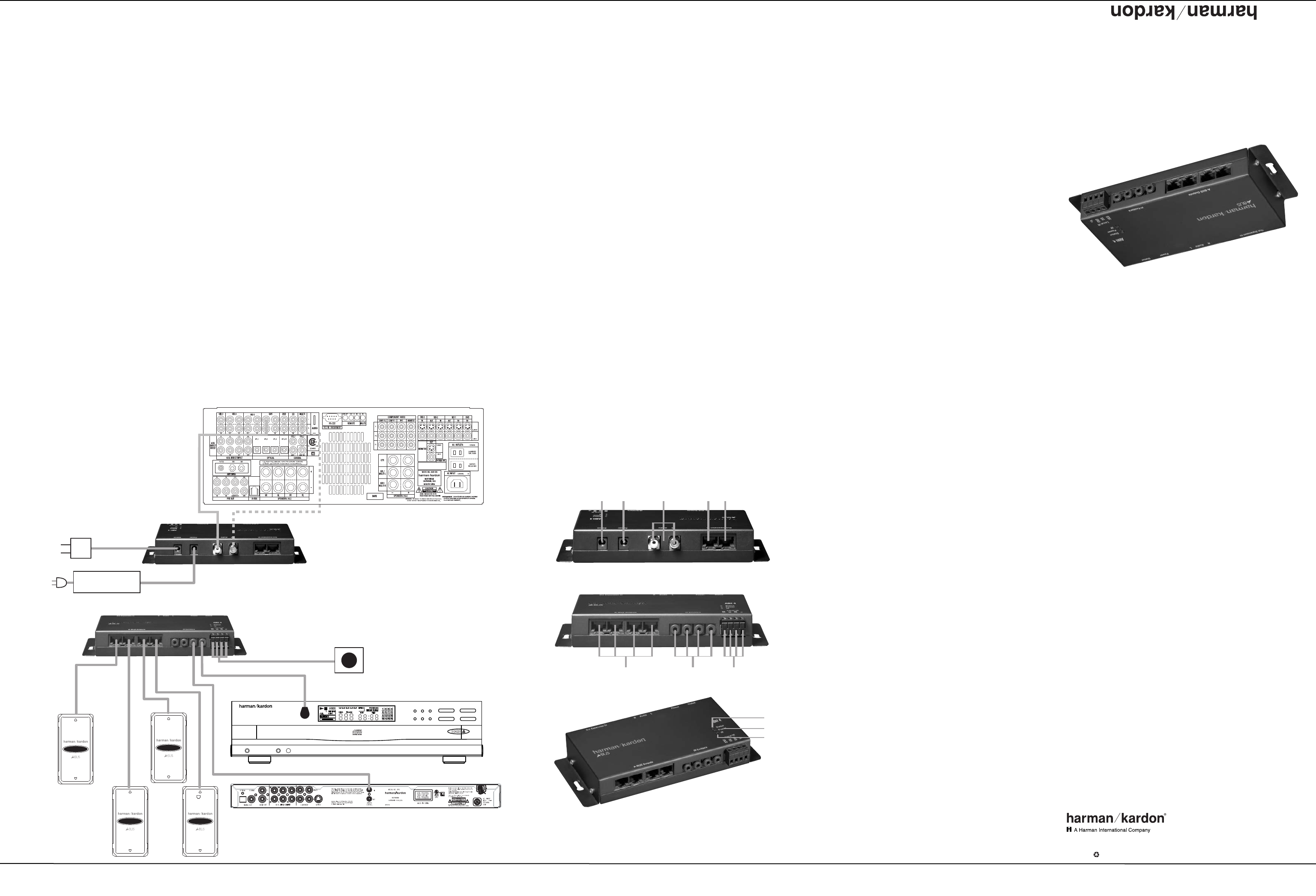
When using the ABH 4 with
non-A-BUS/
READY
r eceiv er s,
connect either the M ultir oom outputs
(i f a vailable ) o r the Tape outputs to
the Audio Input ¢ j ack s on the ABH 4.
DVD player or other sour ce component with
connection to compatible IR input j ack
Connect to either the M ultir oom
or the Tape outputs, but not both.
Optional
IR sensor
Optional 12V
power supply
240240
31
FL 8385
Power Phones Phones Level
PL AY/PAUSE
1 23
45
DIS K SKIP
STOP
SEARCH SKIP
››
Í
‹‹
Sour ce component with optional
IR emitter placed ov er IR sensor
ABH 4
power supply
Power for the
.
®
®
T
¡ Sta
tus Input
™ Power Input
£ Audio Inputs
¢ Expansion In Jack
∞ Expansion Out Jack
Bottom-Edge Connections
§ Local IR Input
¶ I
R Emitter Jacks
• A-BUS Outputs
LED Indicators
å Status Indicator
∫ Power Indicator
ç IR Indica
tor
ABH 4 OM (Large) 3/24/05 4:50 PM Page 2