544880
3
Zoom out
Zoom in
Previous page
1/3
Next page
industrial controls
®
industrial controls
®
NC
CC
GND
+
Spannungs-
versorgung
Steuerlogik
Rohrantrieb
I 5 A
Trafo
Service
Anzeige
Funkempfänger
Antenne
Lerntaste
24 V
Netz
230V / 50 Hz
10 A
Funktionsleuchte
1
2
3
4
DIP
Schalter
+ -
NM PE PE N L1
+ -
Vorendschalter
Externer Taster
I 2 A
Sicherheitsleiste
DW
8,2 k
NOT-AUS
Lichtschranke
Assembly Instructions
Assembly of the logic unit (inside area):
1.
Put the screw-driver into the gap of the enclosure front, push the screw-driver up and
open the enclosure.
2. Remove the control PCB (which is force fitted to the inside of the enclosure).
3. Locate the screwed glands supplied (sealing nipple left side) in the
enclosure and replace the PCB. (Please ensure PCB is firmly in position)
4. Bore the fastening holes and fix the enclosure bracket at the wall.
5. Insert the wires through the cable entry (sealing nipple).
Ensure tight seating of sealing nipple and cable gland, otherwise the water-protection ot
the appliance cannot be assured.
6. According to connection diagram connect the wires to the corresponding terminals:
Safety edge (Option)
The DC2 S has the facility for connection of either a pneumatic or an electrical
safety edge, with no requirement for additional external monitoring/evaluation unit.
If an electrical type safety edge is fitted, the 8,2 k resistor should be connected to the
2 electrical contacts at the end of the safety edge.
If a pneumatic version is fitted the resistor should be fitted in series with the normally
closed contact. Also a pre-limit switch should be installed on the door approximately
50mm from floor level.
Tubular Motor
Care should be taken that the UP and DOWN connections from the tubular motor
to the controller are made in the correct orientation .
The connection should be made with the door in the closed or half-closed position.
If on power-up the door moves in the wrong direction, the power should be broken,
the
and connections reversed, and then the controller should function correctly.
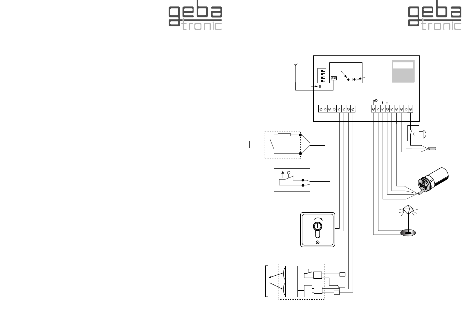
Wiring diagram DC2 S
antenna
DIP-
SWITCH
transformer
radio-receiver
control-light
safety edge
pre-limit-switch
photo-cell
external key-switch
learning push key
tubular drive
power supply
230V / 50 Hz
STOP
button
Attention!
Only a qualified electrician
should make the final power
supply connections!
Service
indicator
3


Need help? Post your question in this forum.

Forumrules


Report abuse

Libble takes abuse of its services very seriously. We're committed to dealing with such abuse according to the laws in your country of residence. When you submit a report, we'll investigate it and take the appropriate action. We'll get back to you only if we require additional details or have more information to share.

Product:

For example, Anti-Semitic content, racist content, or material that could result in a violent physical act.

For example, a credit card number, a personal identification number, or an unlisted home address. Note that email addresses and full names are not considered private information.

Forumrules

To achieve meaningful questions, we apply the following rules:

Register

Register getting emails for Geba Tronic DC2 S at:


You will receive an email to register for one or both of the options.


Get your user manual by e-mail

Enter your email address to receive the manual of Geba Tronic DC2 S in the language / languages: English as an attachment in your email.

The manual is 0,38 mb in size.


You will receive the manual in your email within minutes. If you have not received an email, then probably have entered the wrong email address or your mailbox is too full. In addition, it may be that your ISP may have a maximum size for emails to receive.

Others manual(s) of Geba Tronic DC2 S

Geba Tronic DC2 S User Manual - German - 3 pages


The manual is sent by email. Check your email

If you have not received an email with the manual within fifteen minutes, it may be that you have a entered a wrong email address or that your ISP has set a maximum size to receive email that is smaller than the size of the manual.

The email address you have provided is not correct.

Please check the email address and correct it.

Your question is posted on this page

Would you like to receive an email when new answers and questions are posted? Please enter your email address.


Info