KP500D/
3
5
ITALIANO
A
indicaz
fare riferim
DESCRIZIONE GENER
T
OLED. Ess
MP500 e
sens
dis
all
retroi
sec
Ol
tastiili per
ic
1
POSI
La tasti
:
• in un am
;
• su una par
;
• in pr
;
•
protetto dal
;
• a 160 cm
le i
.
2
C
La tasti
dell
tutte le tr
sc
La sezione dei
tensi
.
Nel c
cons
3
I
La tasti
sc
Per ins
• Sganciar
• Fi
forni
morA” o “B ”.
Evitare di
staffa potr
ste
• Per ilizzedo in corrispondenz
foro “C ”D”.
• CollE”.
• InserirF”.
Dis
dell
dell
• I
• Blocc G” (F
4
COLLEGA
Coll
ri
e Doppio bi
pro
bil
Per ulter
MP500.
5 ACQ
Per l’ac
premF4 presente s
In caso si
nel s
• apr
• pr F4 per c
Per ulter
manual
.
CARATTERISTICHE TECNICH
T
13,8 Vcc
(prel
T 10 Vcc ÷
Corr
a r
ass
ass
ass
32 mA
68 mA
110 mA
200 mA
Lunghezz
Central
400 m
Ti
Serial
Elkr
Ti
dell
Data Fl
Ti
del vocabolar
Data Fl
T -10°C
Um 75%
T -20°C
Grado di IP40 / IK06
Peso 460
Dim 160 x
ENGL
WA: I
produc
panel m
GENERAL DESCRIPTION
Keypad wi
dis
equipped wiiliary
with a vici
that is
above the l
infor
standb
Besi
keys avai
ic
1
PO
Keypad m
:
•
in an en
• on a dr
;
• in the pr
;
• i
temper
;
• at 160 c
ins
.
2
WIRING
Keypad can
along bus
exceed 4
suppl
into ac
In counti
keypad (11
3
INSTALL
T
flus
T
• Rem
• Secure the s
the buil
usiA’ or “B ”. A
they ma
keypad o
• For the anti C" and fi
blocD".
• Connect the c E”.
• Insert th
“F ”
bottom of the ke
ass
• Insert th
• SeG ” (F
Holes
B
Holes
C
Holes
D
Plas
E
Connecti
F
Keypad connec
G
Clos
H
Hole for
Term
board
Descriptio
+
BUS Expansi
+D
BUS T
D
BUS Ke
+IN
Suppliliarnputs
1
auxnput 1
2
auxnput 2
4
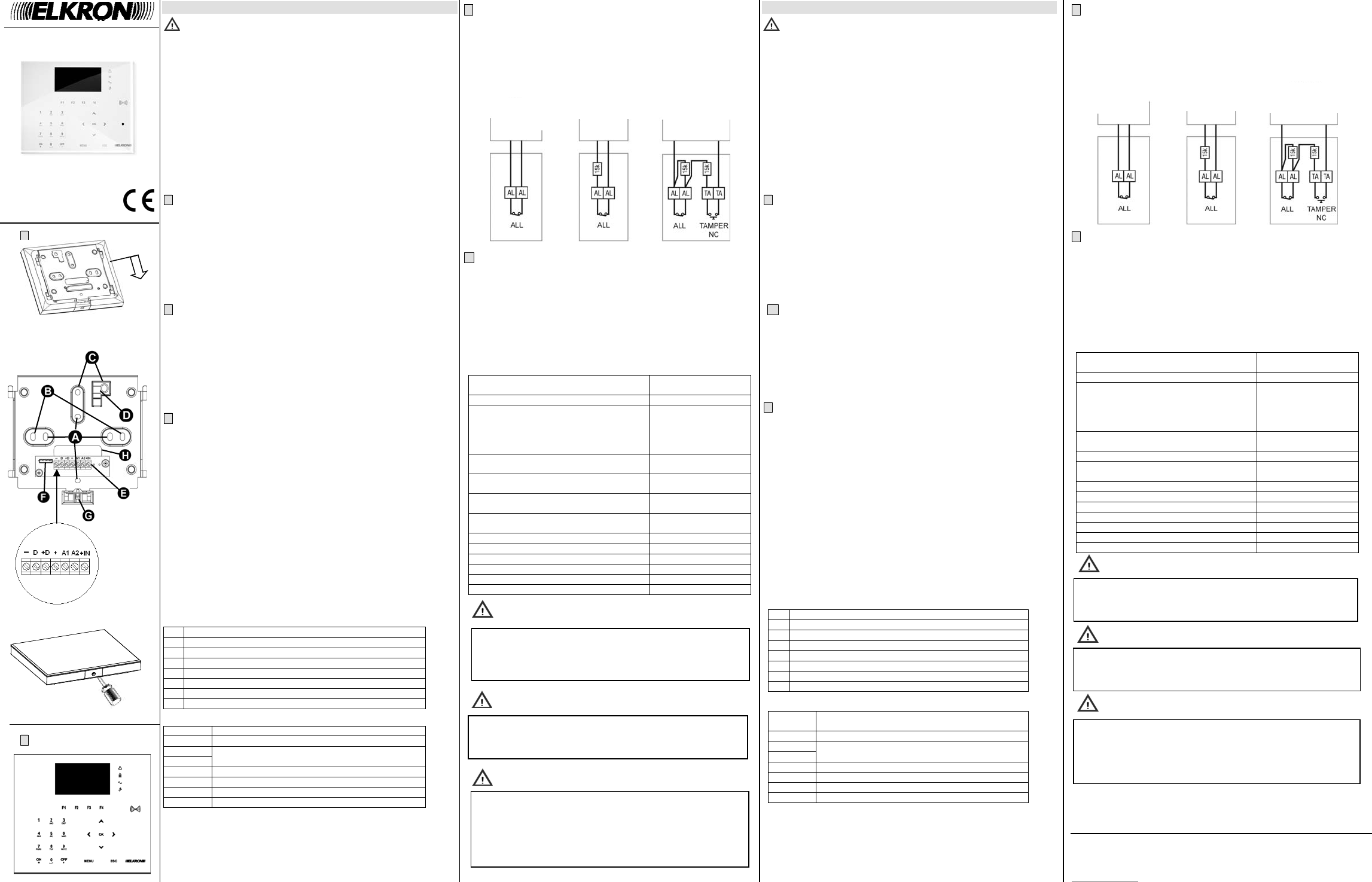
INPUT CONNECTI
Connect aniliarnputs
posi
balanc
rol
kohm res
5
KEYPAD ACQUIRING
TF4 ke
front si
If the parameters
fo
• open th
• push F4 key for abo
For fur
ins
TECHNICA
Nom
13,8 Vd
control
Operati 10 V
Rated cur
In stan
medi
medi
maxim
32 mA
68 mA
110 mA
200 mA
T
Control
400 m
Com ser
Memor
mai
Data Fl
Memor Data Fl
Operati -10°C
Medium 75%
Storage t -20°C
Housi IP40 / IK06
W
Dim 160 x 130
ELKRO
Tel
www.el
ELKRO è un marchi
ELKRON i
URM
Via
www.
Made
A
Fori
B
Fori
C
Fori
D
Inserto plas
E
Mors
F
Connettore t
G
Vite di
H
Foro per
Mo
+
BUS Ingr
+D
BUS T
D
BUS Ingr
+IN
Ali
A1
Ingres
A2
Ingres
Fig.1
Fig.4
In
ins
fo
dirww
NO
tu
ope
non
Da
po
op
bloc
se
a dis
De
pro
CD
WARNING
DO NOT OP all operat
f
int
WARNING
Th
wh
key
pres
will b
la
.
WARNING
Fig.2
ING
NC
ING
BILANCI
ING
BILANCI
NC
INPUT
SI
INPUT
DOUBLE B
INPUT
Fig.3
DS
Tastier
Tou