ER500
Espansione radio
Radio expansion
Extension radio
2
ELKRON
TEL. +39.011.3986711
FAX +39.011.3986703
www.elkron.com –
ELKRON
è un marchio
URMET S
ELKRON is a trademar
ELKRON est une
.
Via Bologna, 188/C - 10154 Torino (TO) – Italy
www.urmet.com
ITALIANO
DESCRIZIONE GENERALE
L’espansione radio ER500 è in grado di gestire una comunicazione radio bidirezionale
a 868,35 MHz, con i dispositivassociati. Attrav
essere connessa direttamente alla centrale filare Elkron, permettendo
gestione mista di dispo
Il numero di dispo
Tipo dispositivo Numero massimo
Sensori (infrarossi IR500; Con 16
Sirene HP500; IS500 2
Telecomandi RC500 4
ATTENZI
In questo documento sono r
relative al prodotto. Per ulteriori e dettagliate in
centrale Elkron in grado di
1
MONTAGGIO
L’espansione radio ER500, può essere monta
riferimento al manuale di Installazione della cenCP/EXP
cod. MP4J00111 in posizione Size(riferirsi
All’interno della cen
Trattandosi di un dispottente/ri
installata con tutte lche delle installazioni di
In caso di u
:
•
in un luogo interno
,
•
in un luogo non so
,
•
in un luogo protetto dall’impian
•
lontano da campi el
.
2
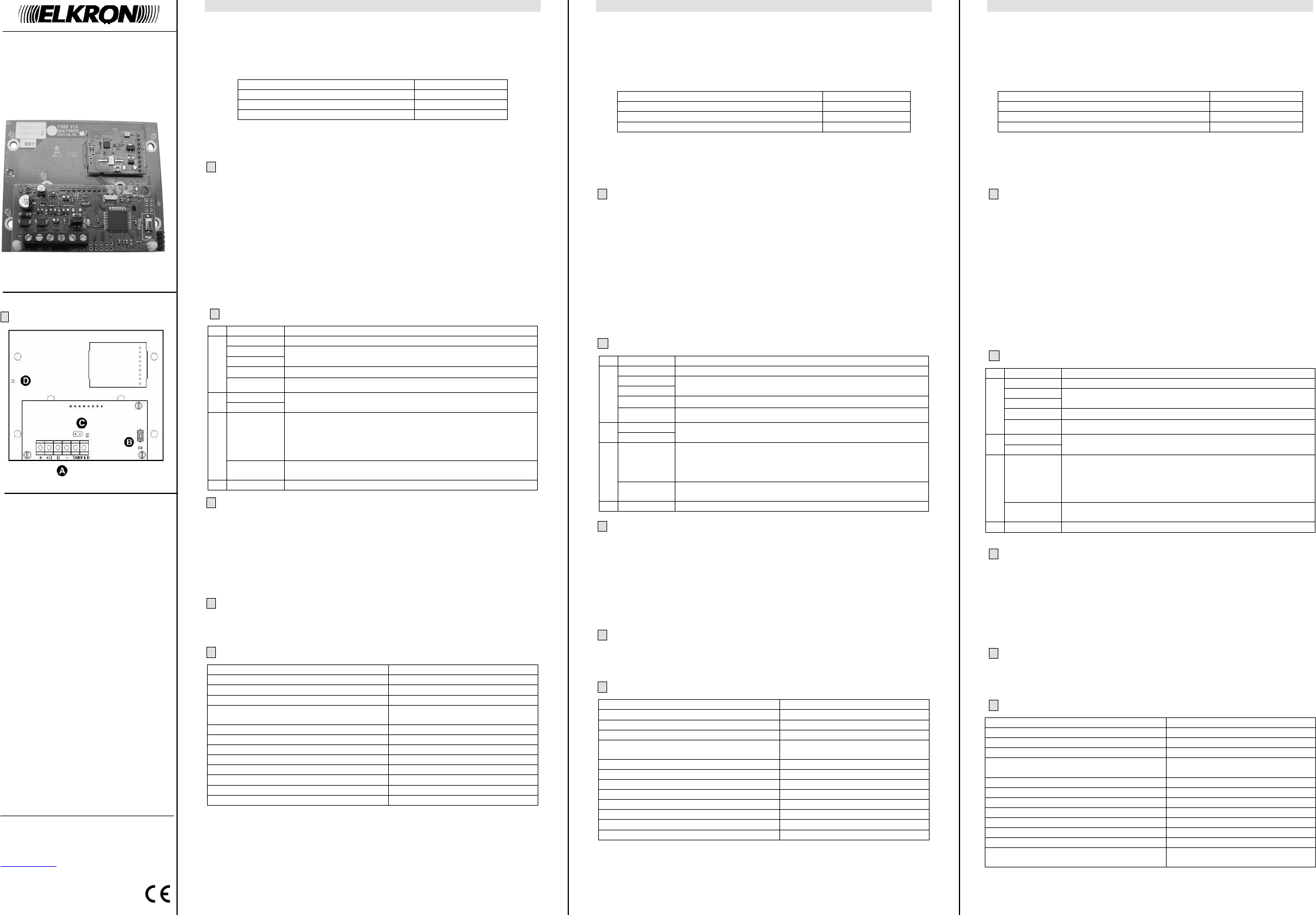
MORSETTI, PULSANTI E LED
Descrizione
+ Alimentazione espansione
+D
D
Trasmissione dati via BUS
–
Alimentazione espansione
A
Tamper Collegamento del microsw
Pulsante
B
LED giallo
Pulsante e Led pe
LED verde
Segnalazione funzionamento (per
Programmazione)
Lampeggiante lento = condizioni di normale funzionamento
Lampeggiante veloce = segnalazione
la centrale da almeno 1
C
Jumper
Ponticello per l’escl
(ponticello inserito
D LED verde Segnala
3
COLLEGAMENTO BUS E TAMPER
L’espansione può casca
La posizione dell’
Collegare l’espansione al+ ”; “+D”; “ D”; “ – ”.
Per il cablaggio usare un cavo schermato a 4 conduttor
collegamento dati). Nel con
consumo max dell’espan
Per l’installazione nel contenitore
Tamper dell’espansione.
4
ACQUISIZ
Acquisire l’espan
“
B
”.
Per ulteriori informazioni su p
d’installazione della cen
.
5
CARATTERISTICHE TECNICHE
Tensione nominale di alimentazione 13.8 Vcc (prelevati tramite
Tensione di funzionamento: 9 Vcc ÷ 15 Vcc
Corrente nominale assorbita a 35 mA
Assorbimento max. corrente pi 45 mA
Lunghezza max. complessiv
seriale Bus Centrale -
400 m
Tecnologia di comunica Radio frequenza bi-direzion
Modalità di comunicazione radio: FSK
Frequenza: 868,35
Numero canali radio: 1
Portata radio: > 100 m in aria libe
Temperatura di funzionamento rata: -5 °C ÷
Umidità relativa di funzionamento: 95 %
Protezione antiapertura Tamper antimanomissione
ENGLISH
GENERAL DESCRIPTION
ER500 radio expansion is able directional 868,35MHz radio communication,
with the associa
By means of a 4 wires bus it could be connected to the Elkron wi
a mixed management of wired and w
Each ER500 radio ex
Device type Maximum number
Detectors (IR500 infrared 16
HP500 and IS500 Sirens 2
RC500 Remote Control 4
CAUTION:
in this document there are only present some essential ind
product.
For further and detailed
handle the ER500 expansion.
1
MOUNTING
ER500 radio expansion cou
installation manual), or inside a wCP/EXP cod. in position Size 1
(refer to the w
Inside the MP508T
Since ER500 is a radio device, this
account all the precautions ty
In case of u
•
in an inner locati
,
•
in a location subjected to
,
•
in a location i
•
far from electromagneti
.
2 TERMINAL BLOCK, BUTTONS AND LED
Description
+ Expansion power supply
+D
D
Data transmission via bus
–
Expansion power supply
A
Tamper Connection for the CP/EXP protection microswitch
Button
B
Yellow LED
Button and LED for ex
Green LED
Working condition (for details see Prog
Slow Blink= n
Fast Blinking = indicates the loss of communication with the
control panel for at
C
Jumper
Jumper for Tamper ex
(inserted = Tamper ex
D Green LED Radio module w
3
BUS AND TAMPER CONNECTION
Expansion can be connected
Expansion position
.
Connect expansion to bu+ ”; “+D ”; “D ”; “─”.
For wiring, use 4 lead screened cable (2 leads for power supply
connection). In cousorption
the expansion.
If installed in the wall box CP/EXP, connehe box Tamper to the Tamper input of the
expansion.
4
EXPANSION CAPTURE
Capture expansion byB ” button.
For further information about acquire procedurrefer to insta
panel.
5
TECHNICAL CHARACTERISTICS
Supply nominal voltage: 13.8 Vdc (taken w
Working voltage: 9 Vdc ÷ 15 V
Nominal current consumption a 35 mA
Maximum current consumption (peak): 45 mA
Control panel-radio ex
max. length:
400 m
Communication technology: Bidirectional radio frequency
Radio communication mode: FSK
Frequency: 868,35
Number of radio channels: 1
Radio range: > 100 m in free ai
Declared operation tempera -5 °C ÷
Working relativ 95 %
Case anti-opening Anti-tamper device
FRANÇA
DESCRIPTION GÉNÉRALE
L’extension radio ER500 permet de gérer une communication radio bidirectio
868,35MHz avec les disposis. L’ex
centrale filaire Elkron par moyquatre conducteurs, permettent une gestion
mixte de dispositifs filaire
Le numéro maximal des dispo
Type dispositif Nombre maximum
Détecteurs (à infrar 16
Sirène HP500; IS500 2
Télécommandes RC500 4
ATTENTI
Ce document contient seulement quelques indication
produit.
Pour obtenir des informations con
capable de gérer l’
1
MONT
L’extension radio ER500 peut ê
manuelle installation de la centrale) ou à l’intérieuCP/EXP cod.
MP4J00111 en position Size 1 (consulter la do
A l’intérieur de lalogée seulemen
Il s’agit de un dispositif radioension doit être installé en tenant
toutes les précautions ty
En cas d’installatio
•
dans un lieu intérie
,
•
dans un lieu à l’abri
•
dans un lieu protégé par un
,
•
éloigné de champs électromagnétiques puissants.
2 BORNES, TOUCHES E LED
Description
+ Alimentation de l’extension via le
+D
D
Transmission des d
–
Alimentation de l’extension via le
A
Tamper Entrée pour le micr
Touche
B
LED Jaune
Touche et LED pour l’acqui
LED verte
signalisation de fonctionnement (pour des détails voir le manuel
de programmation)
Clignotante lente = condition de normal fonctionnemen
Clignotante rapide = signalisation de perte de
centrale pour plus que 1
C
Cavalier
Cavalier pour l’exclusion
(cavalier inséré = a
D LED verte signali
3
RACCORDEMENT DU BUS ET DU TAMPER
L’extension peut êtr
Un positionnement de l’extensio
Raccorder l’extensi+ ”; “+D ”; “D ”; “─ ”.
Pour le câblage, 4
les données). Dan
consommation max. de l'ex
Pour l’installation draccorder l
boitier aux bornes
4
ACQUISIT
Acquérir l’extensionB”.
Pour des informations complémen
manuel d’installation de
5
CARACTERISTIQUE TECHNIQUE
Tension nominale d’alimentation 13.8 Vcc (prélevés à l’
Tension de fonctionnement: 9 Vcc ÷ 15 Vcc
Courant nominale d’alimentation à 1 35 mA
Courant maximale d’alimentation (pic): 45 mA
Longueur max. de la ligne
Centrale
– extension radio
400 m
Technologie de communication: Radiofréquence bidirectionnelle
Modalité de communication radio: FSK
Fréquence: 868,35
Nombre canaux radio: 1
Portée radio: > 100 m en champ
Température de fonctiée: -5 °C ÷
Humidité relative de foent: 9
Protection anti-o Autoprotection con
(tamper)
DS80WL50-001B LBT80735