C
A
T
E
Y
E
MXS
ODO
DST
TM
AVS
CR1620
/CR1616
L
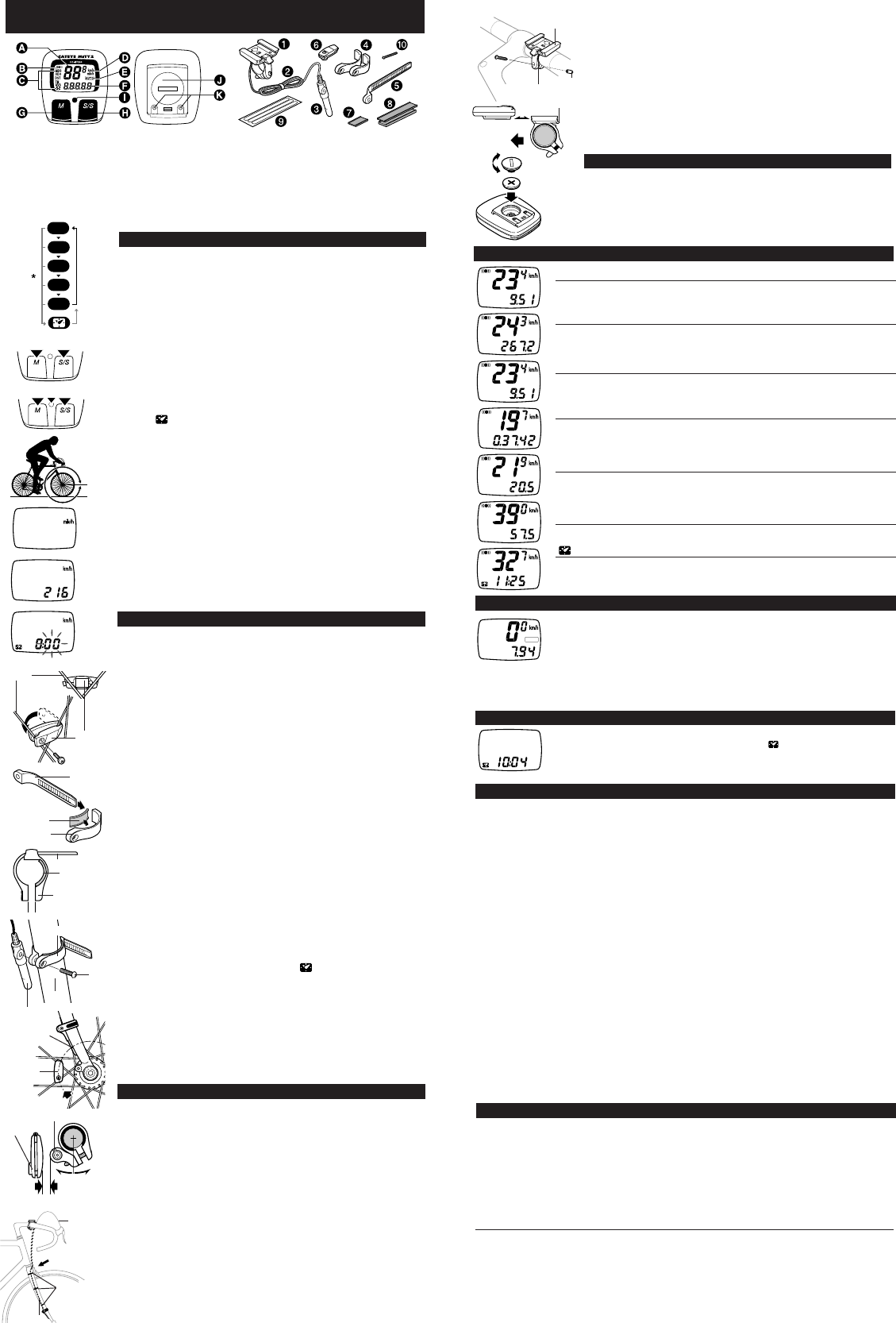
MEASURING AND DISPLAY FUNCTIONS
OPERATING INSTRUCTIONS
E
magnet
sensor
band B
sensor
band A
fork
Fig.12
Fig.10
rubber pad
sensor band B
Fig.11
sensor band A
Fig.17
sporkes
Fig.8
Fig.9
screw
markingline
of sensor
magnet
sensor
Fig.13
wire securing
tape
Fig.14
bracket
screw cap
Fig.15
Fig.16
SPD Current Speed
0.0(3.0) - 65 mile/h(27inch) ± 1 mile/h under31 miles/h
This is always displayed on the main display and updated once a second.
ODO Total Distance (Odometer) 0.0 - 9999.9 mile ± 0.1 mile
This is continuously measured until battery wears down or all clear operation is
done. At 10,000 miles(km), it returns to zero and counting begins anew.
DST Trip Distance 0.00 - 999.99 mile ± 0.01 mile
The trip distance from start to current point is displayed. With Reset operation, it
returns to zero.
TM Elapsed Time 0:00'00" - 9:59'59" ± 0.003 %
Elapsed time is measured from start to current point, in units of hours, minutes
and seconds. At 10 hours, it returns to zero and counting begins anew. With
Reset operation, it returns to zero.
AVS Average Speed 0.0 - 65.0mile/h ±0.3 mile/h
The average speed from start to current point is displayed within 27 hours 46
minutes 39 seconds (99,999 seconds) or 999.99 miles (km). If either is ex-
ceeded, (.E) is displayed and calculation ceases.
MXS Maximum Speed 0.0(3.0) - 65 mile/h(27inch) ± 1 mile/h
With Reset operation, it returns to zero and counting begins anew.
12-hour clock time 0:00' - 11:59' ± 0.003 %
The current time is displayed by a 12-hour clock.
DST
ODO
DST
TM
AVS
MXS
This function switches the main unit to start or stop automatically, in which AUTO
symbol appears on the screen, and you are free from pressing S/S button each
time.
•How to switch on/off the Auto Function.
In TM, DST or AVS, this function switches on/off with each press of SET button.
When on, AUTO symbol appears. *With this function, it ceases measuring
elapsed time during a stop.
*2seconds may be elapsed if mount the main unit to the bracket with this func-
tion on.
AUTO
DST
TROUBLE SHOOTING
• The following situations do not indicate malfunction of the cyclocomputer. Check the
following before taking to repair.
* When current speed does not appear, short-circuit the contact on the back with metal.
The unit will function normally if the speed display appears.
Display response is slow.
----- Ilow temperature under 32° F(0° C)?
----- Ireturns to normal state when temperature rises.
No display.
----- Has the Lithium Battery in the main unit worn out?
----- Replace the Lithium Battery with a new one.
Incorrect data appear.
----- Execute "All Clear" operation.
Current speed does not appear.
----- Ithere anything on the contact of the main unit or of the bracket?
----- Wean.
----- Ithe distance between sensor and magnet too far?
----- Are the marking line of the sensor and the center of magnet matched each other?
----- Refer to "Sensor/Magnet Mounting" and re-adjust correctly.
----- Ithe wire broken?
----- Replace the Bracket & Sensor part with a new one.
Transmission signal loss in damp or wet conditions.
----- Wcondensation may collect between the bracket sensor and the computer causing an
interruption in the data transmission. Wipe the contacts with dry cloth. Contacts can also be
treated with a water repellent silicon jell from an automotive parts or hardware store. Do not
use industrial water repellent; it may damage the bracket.
When the S/S button is pressed, the unit doesn't activate or stop.
----- Iunction?
----- The S/S button doesn't function in the Auto function.
MAINTENANCE/PRECAUTIONS
• Do not leave the main unit exposed to direct sunlight when the unit is not in use.
• Do not disassemble the main unit, sensor and magnet.
• Don't pay too much attention to your computer's functions while riding! Keep your eyes on the
road and duly consider to traffic safety.
• Check relative position of sensor and magnet periodically.
• For cleaning, use neutral detergent on soft cloth, and wipe off later with dry cloth. Do not apply
paint thinner, benzine, or alcohol, to avoid damages on the surface.
• If there is mud, sand or the like clogs between the button and the body, the movement of the
button may be disturbed. Softly wash away such objects with water.
SPECIFICATIONS
Applicable Cycle Sizes 130cm - 229cm
Applicable Fork Diameter 11ø - 36ø (S:11 - 26ø L:21 - 36ø)
The length of the wire 70cm
Power Supply Lithium Battery (CR1620/CR1616) x 1
Battery Life Approx. 3 years(The life of the first factory-loaded battery may
be shorter than this period.)
Dimension/Weight 1-13/16" x 1-5/8" x 9/16" (46 x 41 x 14 mm) / 0.79 oz (22.5 g)
* The specifications and design are subject to change without notice.
center of
magnet
rubber pad
POWER SAVING FUNCTION
ALL CLEAR
RESET
A. Main Display (Speed)
B. Sensor Pulse Symbol
C. Mode Symbol
D. Speed Scale Symbol
E. Auto Mode Symbol
F. Sub-Display (Selected Function)
G. M (Mode) Button
H. S/S (Start/Stop) Button
I. Set Button
J. Battery Case Cover
K. Contact
1. Bracket
2. Wire
3. Sensor
4. Sensor Bands-A (S)(L)
5. Sensor Bands-B
6. Magnet
7.
Sensor Band Rubber Pad
8. Bracket Rubber Pad (2 pcs.)
9. Wire Securing Tape
10. Sensor Band Screw
When main unit is left without receiving any signal for 60-70 minutes continuously,
power supply is shut down and main unit will display ( ) only as the figure. By press-
ing M button or S/S button, or by receiving signal, this function is released.
rubber pad
sensor band A
parallel
sensor
about 2mm
outer cable
wire
lever
OPEN
CLOSE
AUTO (AUTOMATIC START/STOP) FUNCTION
BUTTON FUNCTION
•M button (Fig.1)
Changes the display in the order shown in fig. 1, and data is displayed
on the sub-display. *If held over 2 seconds, 12-hour clock appears.
• S/S button
Starts and stops the measurement of trip distance and elapsed time.
During operation, speed scale symbol flashes. In Auto Function, this
button is invalid.
• SET Button
This is for setting the wheel circumference and clock time, switching on/
off Auto Function and to clear all present data and any irregularity. When
pressed in stop state in each mode, the following can be revised.
• In ODO mode --------------------- Wheel circumference
• In mode ----------------------- 12-hour clock
• In TM, DST or AVS mode ----- On/ unction
Reset Operation: (Fig.2)
Select any mode except ODO, then press M button and S/S button si-
multaneously. MXS, AVS, DST and TM will become zero. (When done in
ODO, registered wheel circumference will be displayed.)
All Clear Operation: (Fig.3)
When M button, S/S and set buttons are pressed simultaneously, all
data stored (ODO, speed scale, Wheel circumference and clock time) is
erased. All displays illuminate, then mile/h symbol illuminates. This
should only be executed after replacing battery or when irregular display
occurs due to static electricity, etc. Since all memories are erased, set
necessary data again according to "Main Unit Preparation".
MAIN UNIT PREPARATION
The following must be completed before operating.
(1) How to measure wheel circumference (L) of your bike (Fig.4)
Put a mark on the tire tread and ride the bike one full wheel revolution.
Mark the start and the end of the revolution on the ground and then
measure the distance between the two marks. This is your actual cir-
cumference. Or, the "Selecting Values Cross Reference Table" tells you
an approximate circumference according to tire size.
(2) Setting Speed Scale
Preform all clear operation. All displays will illuminate. Then mile/h alone
will be displayed as illustrated in fig.5. Km/h and mile/h are alternately
displayed with each press of S/S button. Press M button to set desired
speed scale. The display will change as fig. 6.
(3) Setting the wheel circumference (Fig.6)
The standard wheel circumference of 216 cm for 27" wheel is displayed.
When using 216 cm without revision, press M button. ODO will be dis-
played and 216 cm is set. For revision, press S/S button to increase the
number by one. To increase rapidly, hold down the button. When the
desired number appears, press M button. ODO will be displayed, and
the desired number is set.
(4) Resetting or changing the wheel circumference
Set main unit in ODO with M button, and stop it with S/S button. Press
SET button. The stored number will flicker on the sub-display. Revise
the number as desired according to the instructions in (3).
Setting the clock time (Fig.7)
Press M button over 2 seconds to select , and stop it with S/S but-
ton. Then press SET button, and minutes flash. Press S/S button to ad-
vance minutes by one. To advance rapidly, hold down the button. Set
the time one or two minutes ahead of the current time. Then press M
button, and hours will flash. Use S/S button the same way. Press SET
button to complete time setting. *When you press the SET button, the
undisplayed seconds will turn to zero. For accuracy, set by the radio
time signal.
MOUNTING TO BIKE
• The spokes must run correctly through the inside the magnet as in
fig.8.
• Attach the sensor with Sensor Bands-A-B to the right fork. Choose a
band that fits the fork diameter (S size for up to 24ø, L for oversize).
1. Insert the band-B into the slit of the band-A, and put the rubber pad
inside of the band-A(fig. 9). Adjust the length in order that the
screw-fastening part of the bands are parallel when mounted to the
fork(fig. 10). *To pull out the band B from band A, tug strongly.
2. Mount the adjusted bands to the fork along with the sensor, by tem-
porarily tightening the screw(fig. 11).
3. Align the magnet's center and the sensor's marking line(fig. 12),
and make sure of 2mm clearance between the magnet and sensor
(fig. 13). Then tighten the screw securely. Cut the excess of the
band-B with a nipper or the like.
• Secure the wire with tape as fig. 14. Wind the wire round the outer
cable and adjust length. Loosen the wire in the area marked with the
arrow so that the wire does not hinder handlebar operation.
Fig.6
Fig.7
Fig.4
Fig.5
Fig.1
Fig.2
Fig.3
• Use either 1mm- or 2 mm-thick pads if necessary, according to
handlebar diameter. Attach the bracket close to the handlebar stem
(fig. 15).
• Slide main unit onto the bracket from front until it clicks into position.
To remove, pull it off forward while pushing down the lever. (fig. 16)
•Test (Fig.16)
Mount main unit. If main display does not show any figures, press either
M button or S/S button to release from power saving function. Spin the
wheel to check if sensor pulse symbol flashes. If not, adjust relative posi-
tions of magnet and sensor following the instructions.
HOW TO REPLACE THE BATTERY
Turn main unit over, remove battery case cover with coin and insert a
new lithium battery properly (CR1620 or CR1616) with the (+) pole up-
ward (fig.17), and close the cover securely.
* Please make sure to do the All Clear operation after replacing battery,
and to set the unit again.