ATTENTION
zz
The controller may only be opened by an ex-
pert and to be installed according to wiring dia-
gram inside cover. The current regulations for
safety at work have to be observed.
ÖÖ
Will be achieved by relevant installation
procedures (acc. to VDE 0100) and by cor-
rect mounting on smooth surface non-
conductive and non-flammable.
This controller which can be installed indepen-
dently is designed exclusively for regulating
the temperature indoors in dry and enclosed
rooms under normal environmental condi-
tions.The device confirms to EN 60730, it
works according operating principle 1C
1. Application
●
Electric Floor Heating Systems
●
Hot Water Floor Heating Systems
2. Operation
The controller recognizes the temperature via the ex-
ternal remote sensor.The controller switches on when
sensor temperature is below set temperature and it
switches off as soon as required room temperature
(set value) will be reached and rise.
The setting range 1...4 corresponds to temperature
10...40°C.
The controller can be switched ON and OFF by means
of the rocker switch.
The red LED indicates „calling for heat“
In case of sensor disconnection or shortcircuit the re-
lay will drop.
3. Installation
a) Controller
– System to be wired free of voltage
– Pull off the adjusting knob
– Loosen the fixing screw
– Remove the cover
– Connection acc. to wiring diagram (inside cover)
b) Remote Sensor
Attention:
For more easy replacement sensor cable should
be put into a protection tube. The sensor cable
can be lengthened up to 50 m by using a standard
2-core cable for mains voltage and with a cross
section of 1,5 mm
2
. Close parallel routing along
high voltage cables or in cable ducts should be
avoided or otherwise a screened cable has to be
installed.
Attention:
In case of failure the sensor cable still can carry mains
voltage.
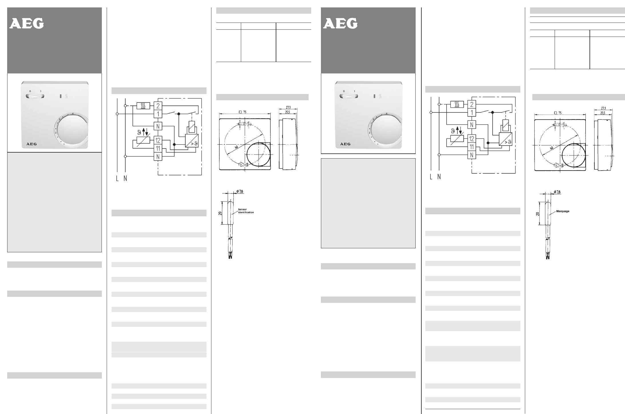
4.Wiring Diagram
Caution: ਠ
Through-connector for earth (PE conductor)
5.Technical Data
Controller Type FTE 600 SN
Switching current 16 A (4 A cos ϕ = 0,6)
Operating voltage at 50 Hz 230 V AC (195 ... 253 V)
Temperature range 1...4 (corresponds to 10...40°C)
Switch mains ON/OFF
Indication LED calling for heat
Contact (Relay) 1 n/o (for „heating“)
Mode of regulation on - off
Switching differential approx. 1 K
Protection class of housing IP 30
Degree of safety II*
Operating temperature –20 ... +40°C
Storage temperature –20 ... +70°C
Degree of polution 2
Calculation impulse voltage 2,5 kV
Temperature for the
Ball compression test 75°C
Voltage and Current for
the for purposes of
interfernce measurements 230 V, 16 A
Remote Sensor
Sensor identification white
Sensing element NTC
Sensor cable PVC (2x0,5 mm2)
Length of cable 4 m
Protection class IP 68
Ambient temperature –25 ... +70°C
* See point ”Attention“
6. Dimensions
Characteristics of NTC resistor
Temperature range 10 . . . 60°C
[kΩ] [V]
10°C 66,8 3,7
20°C 41,3 3,4
30°C 26,3 2,9
40°C 17,1 2,5
50°C 11,3 2,0
60°C 7,5 1,5
Ohmic values only can be tested on disconnected sen-
sor cable
ATTENTION! z
Cet appareil doit être monté et branché selon
le schéma se trouvant dans le couvercle par
un professionnel et dans le respect des
règles de sécurité et des normes en vigueur.
Ö
Est réalisé par un montage sur une sur-
face plane, non conductrice et in inflam-
mable.
Ce thermostat sert à réguler la température
de pièces sèches et fermées dans un envi-
ronnement normal. ICet appareil est selon la
norme DIN EN 60730 et fonctionne selon la
directive 1C.
1. Domaines d’utilisation
●
Chauffage au sol électrique
●
Chauffage au sol par eau
2. Fonctionnement
La température est mesurée par la sonde à distance. Si
celle-ci est inférieure à la consigne, le thermostat en-
clenche le chauffage; si elle est supérieure, le chauffage
sera coupé.
La plage de réglage de 1...4 correspond à une tempéra-
ture de 10…40 °C.
L’interrupteur permet l’arrêt ou la mise en route du ther-
mostat.
La Led rouge signale la mise en route du chauffage.
En cas de coupure ou de court-circuit de la sonde, le
relais de sortie est désexcité.
.
3. Montage
a) Thermostat
– Mettre l’installation hors-tension
– Retirer la molette du thermostat
– Enlever la vis
– Retirer la couvercle
– Brancher selon le schéma (dans le couvercle du
boîtier)
b) Sonde de température
Attention:
Pour faciliter un éventuel remplacement, placer la
sonde dans un conduit de protection
Le câble de sonde peut être prolongé jusqu’à
50 mètres avec un câble:
– de section 1,5 mm
2
– adapté à la tension secteur
Si le câble passe dans des goulottes de câbles ou est à
proximité de conducteurs de puissance, employer du
câble blindé.
Attention:
En cas de défaut, la sonde peut se trouver à la ten-
sion secteur!
4. Schéma de branchement
Attention: ਠ
Connecteur de mise à la terre (conducteur de protection)
. 5. Caractéristiques techniques
Thermostat Type FTE 600 SN
Intensité max 16 A (4 A à cos ϕ =0,6)
Tension à 50 Hz 230 V AC (195…253 V)
Plage de température 1...4 (= 10…40°C)
Interrupteur M/A
Voyant Led Chauffage allumé
Sortie relais 1 contact travail
Régulation Tout ou Rien
Hystérésys env. 1 K
Protection IP 30
Classe protection II*
Température ambiante: –20 … 40 °C
Température Stockage: –20 … 70 °C
Degré d’encrassement 2
Tension assignée de
tenue aux chocs 2,5 kV
Température de test de
compression à bille 75°
Tension et courant pour
les tests de compatibilité
CEM 230 V, 16 A
Sonde
Elément sensible CTN
Cable PVC (2 x 0,5 mm
2
)
Longueur 4 mètres
Protection IP 68
Température ambiante: –25 … 70 °C
* Voir point »Attention«
6. Dimensions
Caractéristiques de la sonde
Couleur de la sonde: blanche
Température de la sonde 10 . . . 60°C
[kΩ] [V]
10°C 66,8 3,7
20°C 41,3 3,4
30°C 26,3 2,9
40°C 17,1 2,5
50°C 11,3 2,0
60°C 7,5 1,5
les valeurs ohmiques ne peuvent être mesurées que
sonde débranchée!
468 931 0003291-1
╞
Instructions for use
and assembly
Temperature Controller for
Floor Heating Systems
Typ FTE 600 SN
468 931 0003291-1
╘
Notice de montage
et d’utilisation
thermostat pour
chauffage par le sol
Typ FTE 600 SN
Errors possible-subject to alterations 280922/34615/2/0743
Sous rèserve d'erreurs 280922/34615/2/0743