5IN2000DE
Deutsch
Bedienungsanleitung XEVOX 3600
Plazieren des Melders
Vor der Montage des Melders sollten Sie die folgenden Punkte
berücksichtigen:
•Wählen Sie eine Stelle, von der aus die Erfassung einer Person durch
den Bewegungsmelder im Falle eines Einbruchs am b
•Befestigen Sie den Melder im Zentrum des abzusichernden B
•Richten Sie die Erfassungssektoren des Melders zum Boden aus.
•Vermeiden Sie die unmittelbare Nähe von Radiatoren, Heizungs- bzw.
Kühlrohren oder Lüftungsausgängen von Klimaanlage
•Plazieren Sie den Melder nicht an Stellen in Fensternähe, die
unmittelbarem Sonnenlicht oder Zug ausgesetzt sind.
Installationsanweisungen
1. Öffnen Sie das Gehäuse, indem Sie die Meldergrundplatte festhalten
und den Deckel mit der anderen Hand im Uhrzeigersinn drehen (Fig. 1).
Fig. 1
Anmerkung: Vermeiden Sie jegliche Berührung mit dem IR-
Element.
2. Öffnen Sie die erforderlichen Montage- und Kabellöcher auf dem
Melderunterteil.
3. Führen Sie das Kabel durch die Kabeleinlässe (von der Außenseite der
Einheit) in das Gehäuse.
4. Befestigen Sie den Melder an der dafür vorgesehenen Stelle.
5. Befestigen Sie die Zugentlastung (Kabelbinder) so an der Leitung im
Inneren des Gehäuses, dass der Kabel sich nicht mehr aus dem Gehäuse
heraus ziehen lässt
6. Verbinden Sie die Drähte mit den Anschlussklemmen (Fig. 2).
7. Versiegeln Sie die Öffnung der Kabeleinlässe mit Silikon zum Schutz
vor Staub und Insekten.
Betrieb und Ausrichtung
Einstellung des Impulszählers:
Der Impulszähler regelt die Anzahl von Impulsen, die erkannt werden
müssen, bevor der Melder das Alarmrelais öffnet. Die Einstellung des
Impulszählers kann über den jeweiligen Dipp-Sc
werden. Nur ein Schalter darf für eine spezielle Impulswahl ausgewählt
werden. Werkseinstellung ist Impulswahl 2.
Einstellung der LED Anzeige/Geh-Test:
Wählen Sie am Dippschalter die folgenden Einstellungen:
PULSES:
LED:
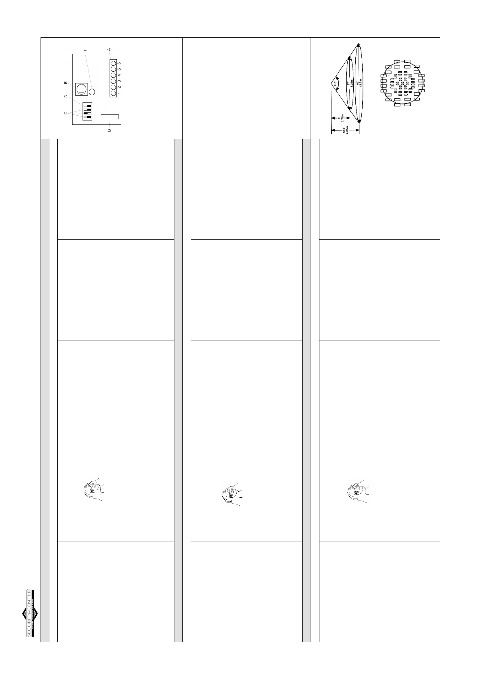
Bei geschlossenem Deckel leuchtet nun stets bei einer Erfassung die LED
auf. Dadurch kann die Funktionalität der LED und der Erfassungsbereich
des Melders getestet werden. Beachten Sie hierzu bitte auch das
Diagramm des Erfassungsbereiches (Fig 3). Setzen Sie nach dem Test die
LED-Funktion wieder auf OFF, damit bei normalen Bedingungen ein
Eindringling nicht bemerkt, dass er erfasst wurde.
Beachten Sie bitte, dass das Gehäuse zum Testen
geschlossen sein muss!
Technische Daten:
Betriebsspannung: 9-16V DC (nom.12VDC)
Stromaufnahme: 15mA bei 12VDC
Alarmkontakt: NC, 50mA, 24VDC max.
Sabotagekontakt: NC, 0,5A, 24VDC max.
Erfassungsbereich: Öffnungswinkel 0 , Übersicht 3600
Impulszähler: 1,2,3
LED Anzeige: wählbar (Steckbrücke)
Pyroelement: duales
RF-Immunität: 30V/m bis zu 1GHz
Betriebstemperatur: -100 bis +550 C
Lagertemperatur: -200 C bis +600 C
Abmessungen (Ø , H): 135mm, 27mm
Gewicht: 118g
English
Fig. 2
Manual XEVOX 3600
Detector placement
Before mounting the detector, you should observe the following:
•Choose a place where it is most likely that a person will be detected by
the motion detector in the event of a burglary.
•Mount the detector in the centre of the protected area.
•Arrange the detector to the ground.
•Avoid immediate proximity to radiators, heating and refrigeration pipes,
and air conditioning ventilation outlets.
•Do not place the detector near a window where it may be exposed to
direct sunlight or draught.
Installation instructions
1. Open the housing by removing the front cover. This is done by holding
the base plate with the right hand and simultaneously turning the top
cover clockwise with the other hand.
Fig. 1
Note: Avoid any contact with the IR component.
2. Open the required mounting and cable holes.
3. Feed the cable into the housing through the cable inlets (from the
outside of the unit) and
4. Mount the detector on the blanket.
5. Attach the strain relief with the cable inside the bottom cover. Pay
attention that the cable can not be pulled out of the cover.
6. Seal the opening of the cable inlets with silicon to protect against dust
and insects.
7. Attach the wires to the connection terminal (Fig. 2).
Operation and orientation
Setting the pulse counter:
The detector is supplied in the 3 pulse count mode. The adjustment of the
counter can be changed by setting the “Pulses” DIP switch. Only one
switch can be chosen for a special pulse. Normally the setting is pulse 2 .
Setting the LED indicator/Walk-test:
Select the following settings at the DIP switch:
PULSES:
WALK-TEST:
If the cover is closed the LED should light up every time a motion will be
detected. Due to this setting the functionality of the LED and the detection
range of the detector can be tested. Please pay regard to the detection
diagram (Fig. 3). After testing the functions set the LED again to OFF so
that under normally conditions a intruder will not recognize that he has
been detected.
Note: Ensure that cover is installed after mounting and wiring. Do
not check or test detector without cover closed.
Technical specifications:
Input voltage: 9-16V DC (nom.12VDC)
Current consumption: 15mA at 12V
Alarm contacts: NC, 50mA, 24VDC max.
Tamper contacts: NC, 0.5A, 24VDC max.
Coverage: 1100 angle, 3600 overview
Puls count: selectable 1,2,3 (DIP switch)
LED indicator: selectable (jumper)
Pyroelement: dual PIR element
RF immunity: 30V/m. up to 1GHz
Operating temperature: -100 to +550 C (140 to +1310 F)
Storage temperature: -200C to +600 C (-40 to +1400 F)
DimensioØ , H): 135mm, 27mm
Weight: 118g
FRANÇAIS
A: Connection Terminal/Anschlussleiste/Bornes de rec
B: Tamper Contact/Sabotage/Contacte Autoprotection
C: DIP-Switch puls counter/Dipp-Schalter Impulszähler/
Compteur d’impulsion.
D: DIP-Switch LED/ DIP-Schalter LED/DIP- Interrupteur DEL
E: PIR element/ Composent PIR
F: LED/DEL
Connection Terminal/Anschlussleiste/Bornes de raccordement
1&2 Tamper/Sabotage/Autoprotection
3&4 Alarm/Alarme
5&6 Voltage input (GND, +12V) /Spannungseingang /
Alimentation de tension
Instructions d’installation XEVOX 3600
Positionnement du détecteur
Préalablement au montage:
•choisir un site permettant au détecteur de mouvement la meilleure
détection possible d’une personne, en cas d’effraction.
Fixer le détecteur à la hauteur de montage conseillée à savoir 2,5 m.
•Ne pas masquer le détecteur par des rideaux ou des objets encombrants
•Eviter la proximité de radiateurs, de tuyaux de chauffage ou de
refroidissement, voir les sorties d’aération du système de climatisation
•Ne pas placer le détecteur à des endroits proches des fenêtres ni
directement exposés au courant d’air
Instructions d’installation
1-Ouvrir le boîtier, bien tenir le détecteur avec la main droite et tourner le
couvercle avec la main gauche dans le sens contraire des aiguilles de la
montre.
Fig.1
Remarque: éviter chaque contacte avec l’élément IR.
2. Ouvrir les perforations de câblage et de montage nécessaires du
détecteur.
3. Entrer le câble dans par les perforations du boîtier et fixer le détecteur
dans la position souhaitée. Prendre en considération que les bornes de
raccordement de la platine indiquent la longue zone de détection (13m
ou 8m), tandis que la face opposé indique le zone de détection étroite.
(Fig .2)
4. serrer l’attache câble de telle façon que les câbles à l’intérieur du
boîtier soient bien fixer.
5. Brancher les câbles avec les bornes de raccordements (Fig. 1).
6. Pour la protection contre la poussière et les insectes, Colmater
l’ouverture des entrées de câbles à l’aide de silicone.
7. Refermer le boîtier et fixer le couvercle de l’installation VDS
(les vis sont livrées). Prendre en considération que le couvercle soit bien
placé.
Mise en service et orientation
Réglage du compteur d’impulsion : le compteur d’impulsion règle le
nombre d’impulsion qui doivent être reconnues avant le déclanchement
de l’alarme. Le réglage de compteur d’impulsion peut être changé par le
biais des interrupteurs (1,2,3). Seul un interrupteur peut être choisi.
Réglage d’usine est de 2 impulsions.
Réglage de la DEL d’indication /Test de fonctionnement
Choisir ces options d’interrupteur:
PULSES:
WALK-TEST: ON (Test de fonctionnement)
-Réglage de la DEL d’indication :
Mettre le cavalier pour activer la DEL d’indication et l’enlever pour la
désactiver.
-Temps de stabilisation :
Après l’alimentation d’une tension de 9-16V DC, le détecteur à besoin de
3 min pour la stabilisation.
-Test de fonctionnement :
Un test de fonctionnement est performé afin de déterminer si le détecteur
est en fonctionnement total. Pour faire cela, passez à tr
couverture du détecteur (référez vous la figure 3). Contrôler la DEL pour
assurer une couverture complète. Ce test doit être fait chaque semaine.
Si le couvercle est fermé, la DEL clignote chaque foie en cas de détection.
Comme ça le fonctionnement de la DEL et de la zone de détection peut
être testé. Prendre s.v.p le diagramme des zones de détection (Fig.2).
Après le test de fonctionnement remettez le WALK-TEST sur OFF, pour
qu’en cas de détection le DEL d’indication n’indique pas que le
cambrioleur a été détecté.
Remarque : Prière de prendre en considération que le détecteur doit être
fermé avant d’effectuer le test.
Fiche technique :
Tension d’alimentation : 9-16V DC (nor.12VDC)
Consommation du courant : 15mA / 12V
Relais d’alarme NC, 50mA, 24VDC max
Relais d’autoprotection : NC, 0.5A,
Zone de couverture :
Compteur d’impulsion: sélectionnable 1,2,3 (Interrupteur)
Durée d’alarme: minimu
Del d’indication: Sélectionnable pont enfichable
Composent Pyro : Composent PIR dual
Immunité RF: 30V/m jusqu’à 1GHz
Temp. de fonctionnement: -10° jusqu’à +55°C
Temp. de stockage: -20° jusqu’à +60°C
Dimension: 135mm,
Poids: 118g
Fig. 3